This helps you quickly interpret patents by identifying the three key elements:
Problems solved by technology
Method used
Benefits of technology
Benefits of technology
[0010] An aspect of the present invention is to solve at least the above problems and/or disadvantages and to provide at least the advantages described below
Problems solved by technology
However, such connection between the driving motor and the brush member causes a complicated structure and increases the manufacturing cost.
However, when the turbine unit is used to rotate the brush member, the dust drawn in through the suction path may be caught in the turbine unit.
Especially, when small particles such as hair and fine dust are caught in the turbine unit, the rotative force of the turbine unit may be decreased due to low inertia and low torque of the turbine unit.
Method used
Image
Click on the blue label to locate the original text in one second.
Reading with bidirectional positioning of images and text.
Examples
first embodiment
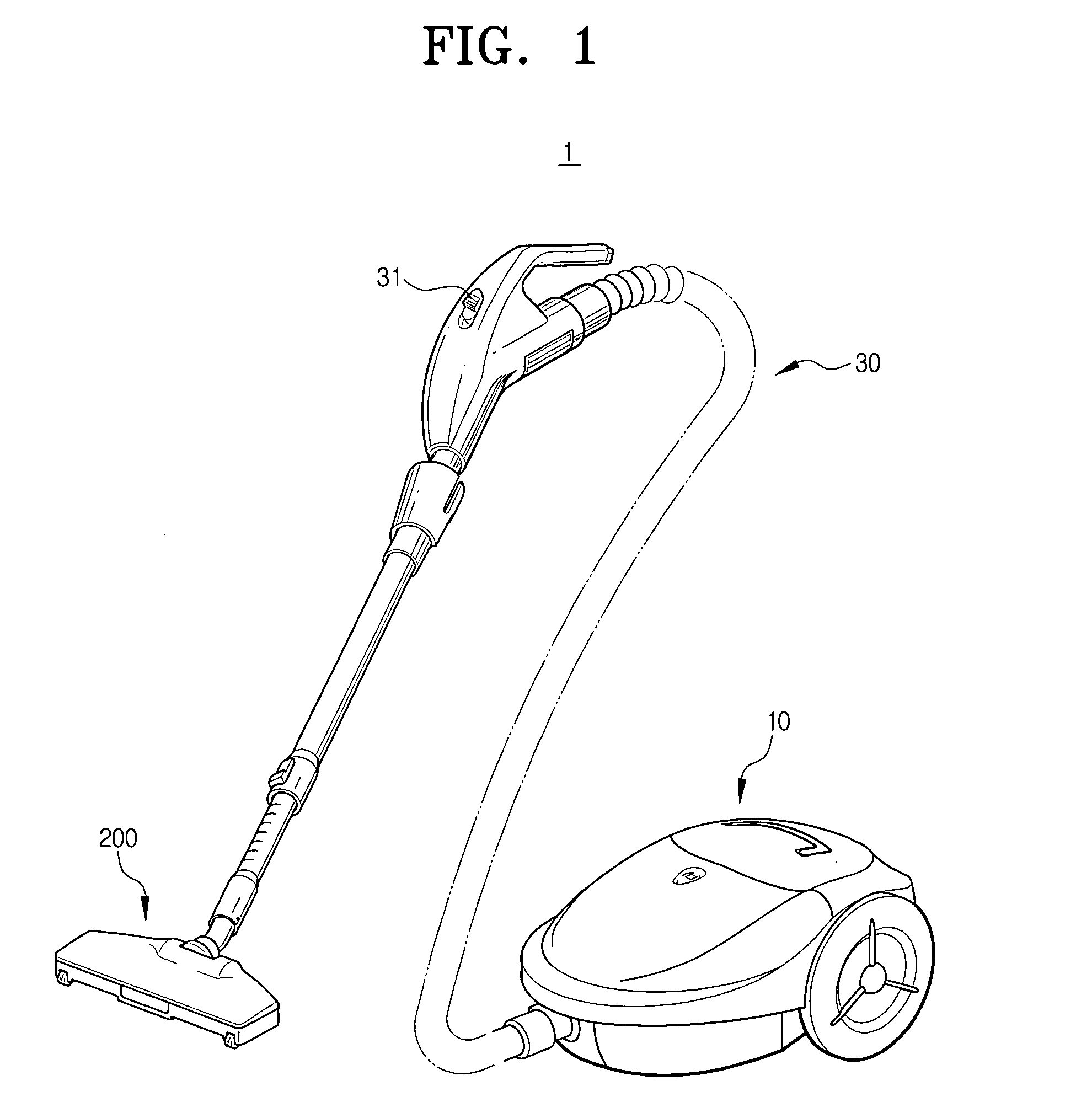
[0034]FIG. 1 is a perspective view of a vacuum cleaner employing a turbine brush according to the present invention.
[0035] Referring to FIG. 1, the vacuum cleaner 1 comprises a cleaner body 10 including a vacuum generator (not shown) and a dust collecting chamber (not shown), a turbine brush 200 for drawing in dust from a surface being cleaned, and a connection member 30 for connecting the cleaner body 10 and the turbine brush 200. The connection member 30 comprises an operation switch 31 for turning on and off the vacuum cleaner 1.
[0036] The vacuum generator (not shown) generates a suction force for drawing in the dust separated from the surface being cleaned. General driving motors can be applied for the vacuum generator. The dust collecting chamber (not shown) collects therein the dust drawn in by the suction force of the vacuum generator.
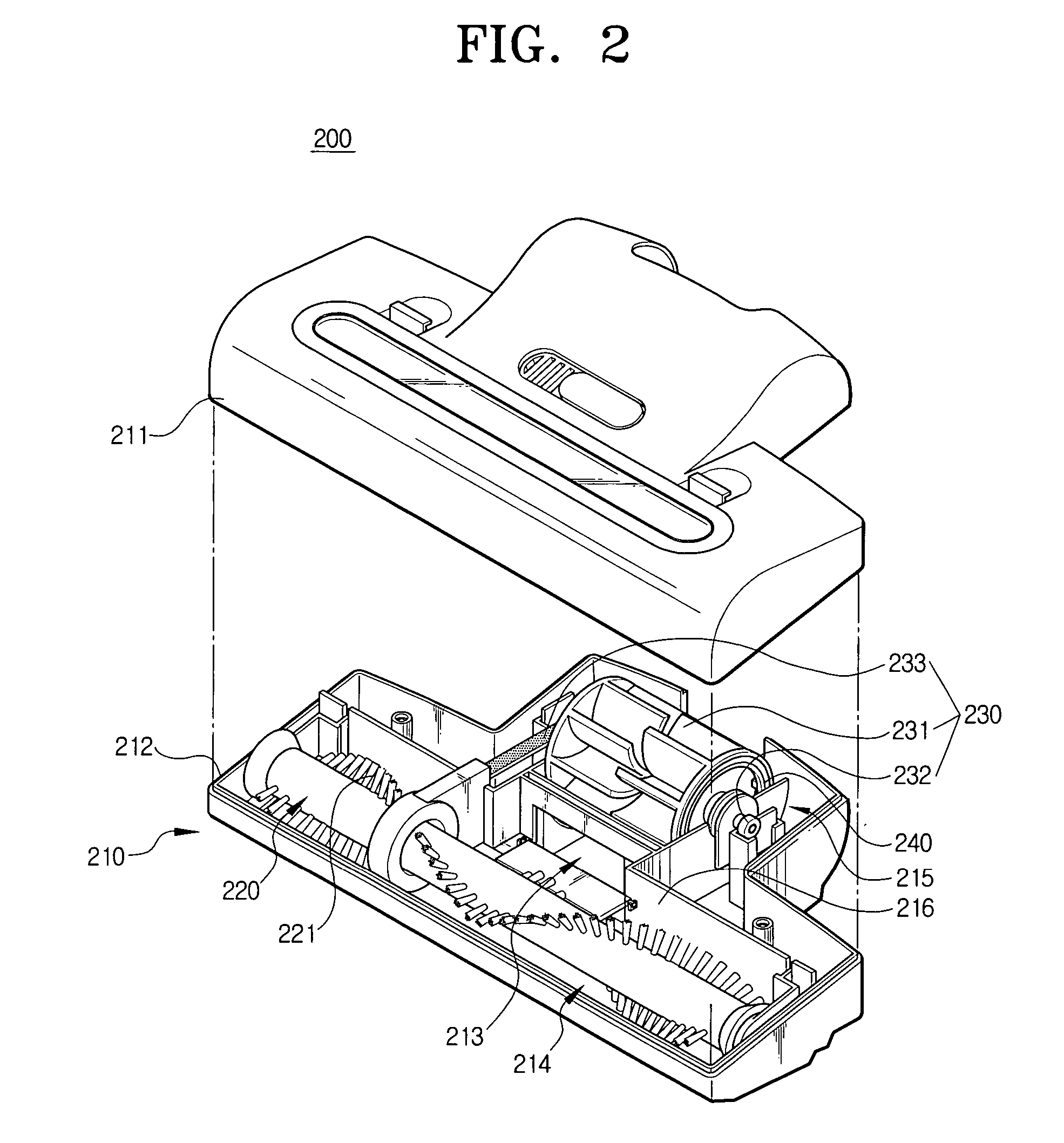
[0037] As shown in FIG. 2, the turbine brush 200 comprises a turbine brush body 210, a brush member 220, a driving unit 230 and an inertia me...
second embodiment
[0058] The turbine brush according to the present invention comprises the turbine brush body 210 and the brush member 220 with the same structures as shown in FIG. 2 and the driving unit 330 with the same structures as shown in FIGS. 5 and 6.
[0059] The detailed descriptions and drawings of same structures as the aforementioned first embodiment will be omitted in the present second embodiment, and the following third and the fourth embodiments.
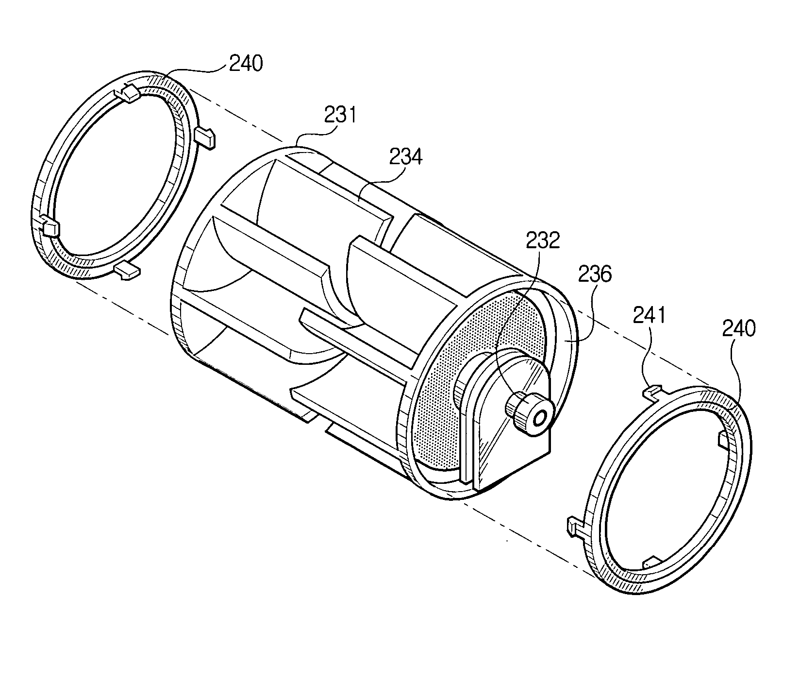
[0060] The driving unit 330 according to the second embodiment of the present invention comprises the turbine 331, the turbine shaft 232, and the power transmitter 233 (refer to FIG. 2). The technical constructions of the turbine shaft 232 and the power transmitter 233 are the same as described with reference to FIG. 2.
[0061] The turbine 331 is rotated by air drawn in through the suction path 213 and having a plurality of blades 334 with thickness-varying portions in a direction of radius Rb.
[0062] More specifically, arcs of the blades 334 o...
third embodiment
[0066] Referring to FIG. 7, the turbine brush according to the present invention is characterized of a turbine 431 having a plurality of blades 434 with increasing thickness Tb in the direction further away from the turbine shaft 232. The thickness Tb of the blade 434 increases in proportion to the length in the radius direction Rb. Therefore, more weight can be added to the blade 434 and increase the inertia.
PUM
Abstract
A turbinebrush for a vacuum cleaner according to an embodiment of the present invention, comprises a turbinebrush body connected to a cleaner body in which a suction force is generated and having a suction path therein, a brush member rotatably mounted to the turbine brush body, a driving unit rotatably mounted in the turbine brush body to drive the brush member, and an inertia member for adding inertia to a driving force of the driving unit. Accordingly, a rotative force is not deteriorated even by small particles such as fine dust and hair, owing to the inertia added to the turbine, thereby improving a cleaning efficiency.
Description
CROSS-REFERENCE TO RELATED APPLICATIONS [0001] This application claims benefit under 35 U.S.C. § 119(a) of Korean Patent Application Nos. 2005-19963 and 2005-31545, filed Mar. 10, 2005 and Apr. 15, 2005, the entire contents of which are incorporated herein by reference. BACKGROUND OF THE INVENTION [0002] 1. Field of the Invention [0003] The present invention relates to a vacuum cleaner. More particularly, the present invention relates to a turbine brush of a vacuum cleaner, rotated by a turbine to remove impurities on a surface being cleaned. [0004] 2. Description of the Related Art [0005] In general, vacuum cleaners comprise a brush member for drawing in dust on a surface being cleaned in contact with the surface being cleaned. Moving along the surface being cleaned, the brush member scratches or beats the surface being cleaned by a rotative force, thereby separating the dust from the surface being cleaned. The separated dust is drawn into a main body of the vacuum cleaner by a suc...
Claims
Application Information
Patent Timeline
Application Date:The date an application was filed.
Publication Date:The date a patent or application was officially published.
First Publication Date:The earliest publication date of a patent with the same application number.
Issue Date:Publication date of the patent grant document.
PCT Entry Date:The Entry date of PCT National Phase.
Estimated Expiry Date:The statutory expiry date of a patent right according to the Patent Law, and it is the longest term of protection that the patent right can achieve without the termination of the patent right due to other reasons(Term extension factor has been taken into account ).
Invalid Date:Actual expiry date is based on effective date or publication date of legal transaction data of invalid patent.

