Outer shell structure for a heat exchanger

Inactive Publication Date: 2006-09-14
XENESYS
View PDF7 Cites 19 Cited by
  • Summary
  • Abstract
  • Description
  • Claims
  • Application Information

AI Technical Summary

Benefits of technology

[0029] According to the ninth aspect of the present invention, the inlet and outlet for the other heat exchange fluid, which are provided on the opposite sides of the heat exchanger, respectively, are placed in the vicinity of the first walls with an opening of the heat exchanger, that are spaced apart from each other so that the other heat exchange fluid flows from one end of the second gap portion of the heat exchange unit to the other end thereof. It is therefore possible to

Problems solved by technology

However, a high pressure of the heat exchange fluid flowing between the plates may cause deformation of the gasket member, thus disabling an appropriate separation of the fluids from being ensured or leading to an unfavorable variation in distance between the plates.
In such a case, an effective heat exchange may not be carried out, thus causing a problem.
In view of these facts, the conventional heat exchanger involves a problem that the heat exchange fluids can be utilized only in a pressure range in which the gasket member withstands.
However, the passage extends in the direction from one side to the other side of the plate and then turns back to the one side in the reverse direction and repeats such extension, leading to a larger loss and deteriorated heat exchange efficiency in comparison with a heat exchanger having a flowing relationship in which flu

Method used


Image

  • Outer shell structure for a heat exchanger
  • Outer shell structure for a heat exchanger
  • Outer shell structure for a heat exchanger

Examples


first embodiment

of the Present Invention

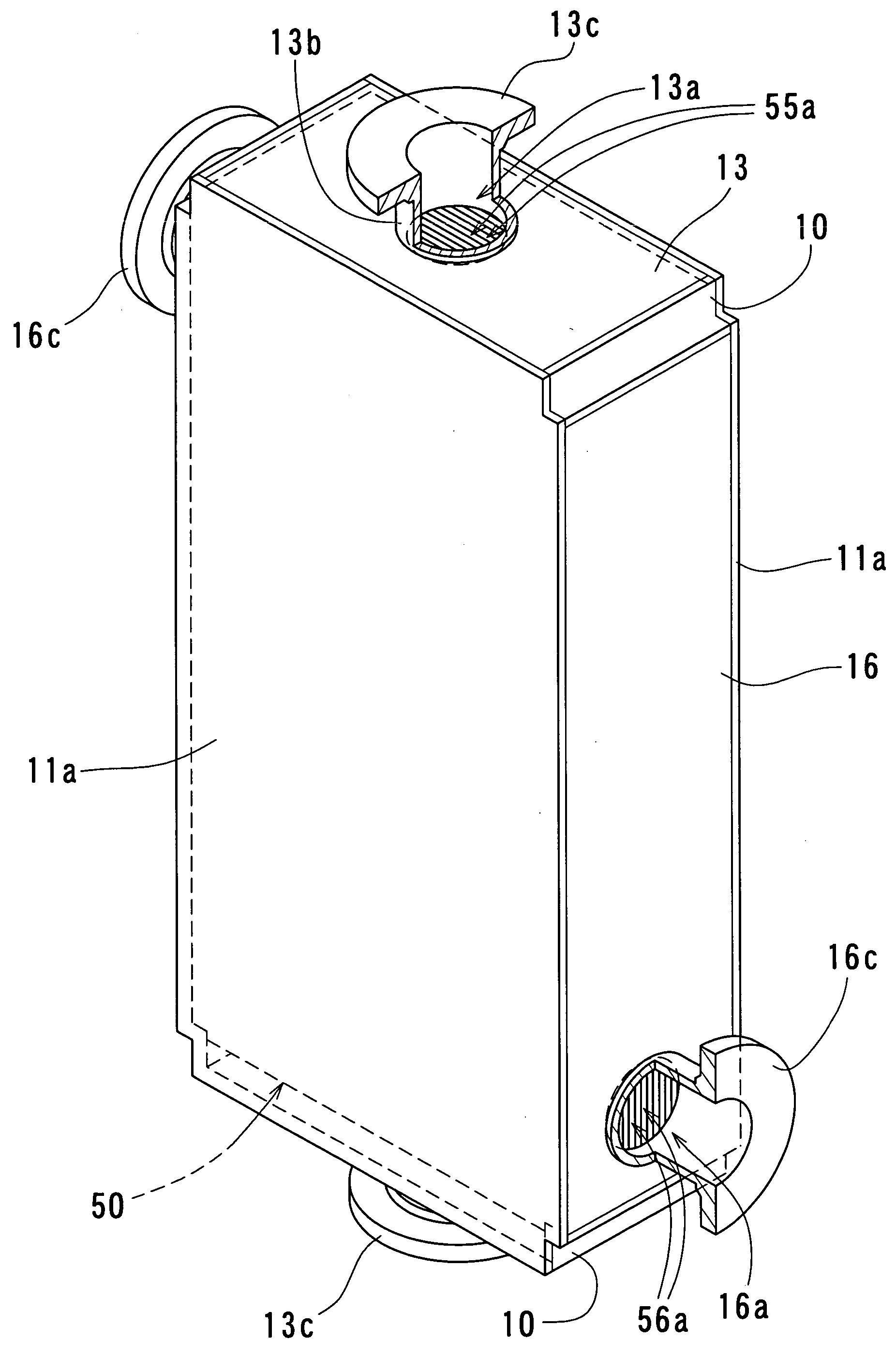
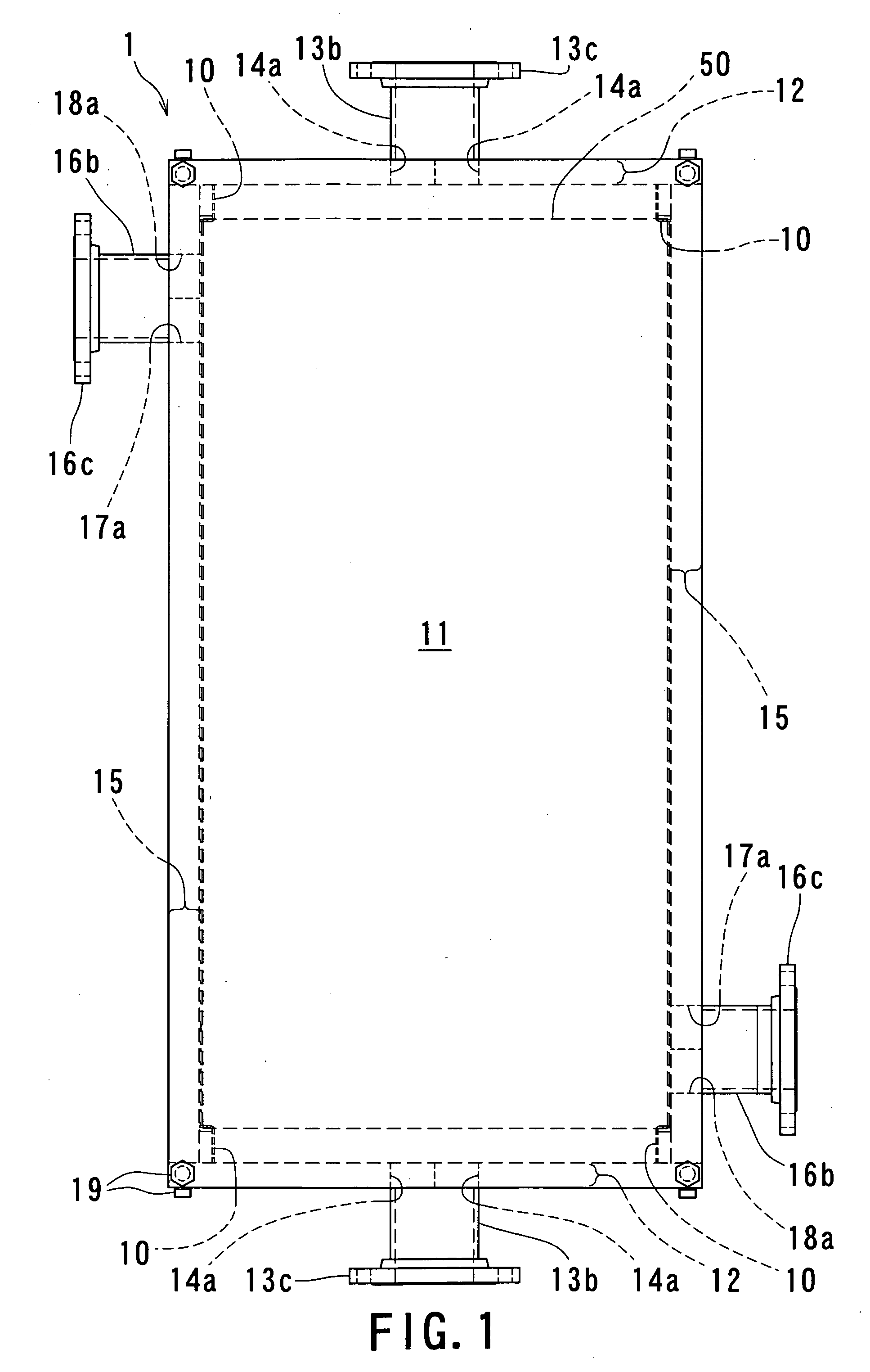
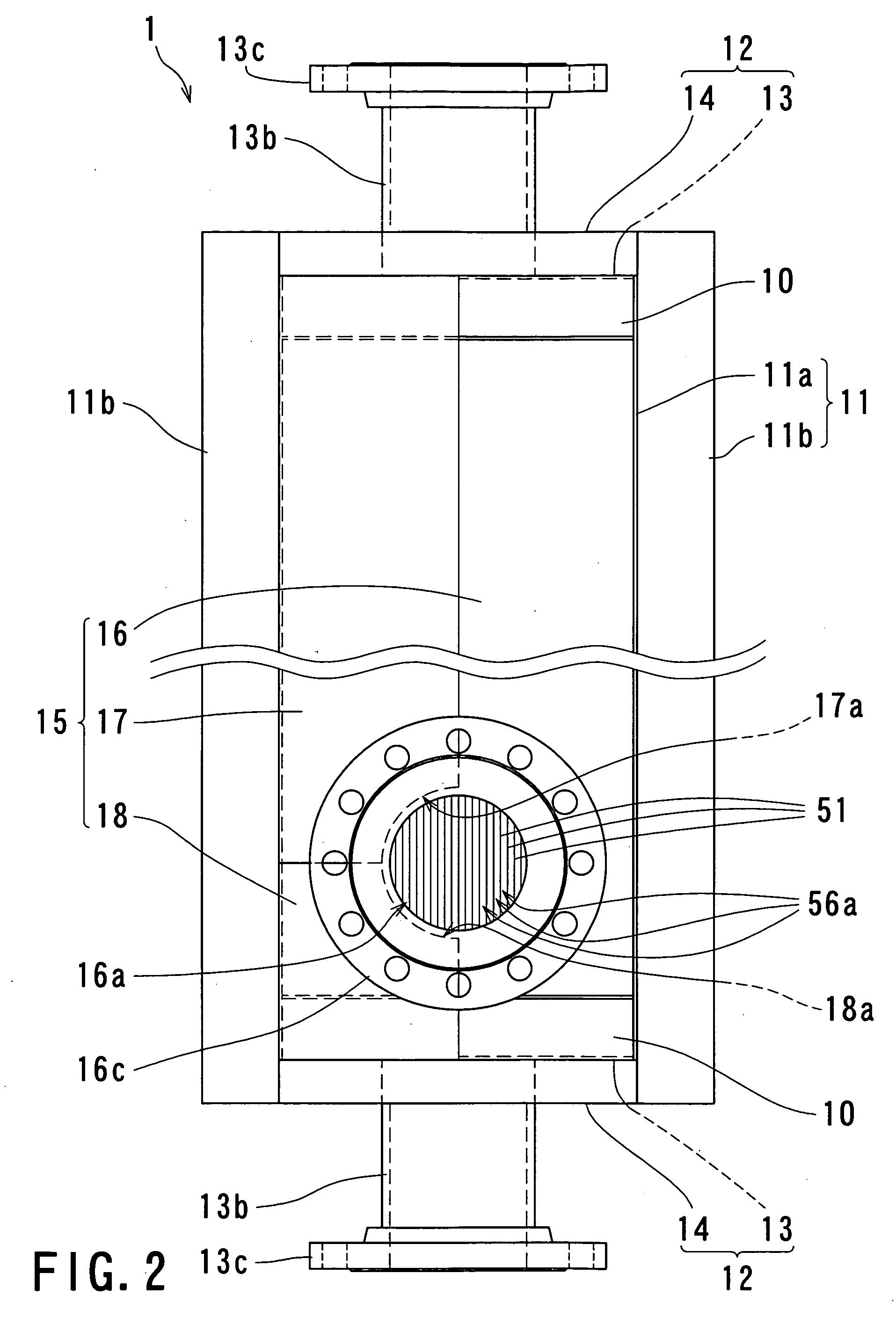
[0052] Now, the first embodiment of the present invention will be described in detail below with reference to FIGS. 1 to 10. FIG. 1 is a front view of a heat exchanger according to the first embodiment of the present invention; FIG. 2 is a partially enlarged left-hand side view of the heat exchanger according to the first embodiment of the present invention; FIG. 3 is a partially enlarged bottom view of the heat exchanger according to the first embodiment of the present invention; FIG. 4 is a descriptive view illustrating a state in which a corner ridge member and an inner plate are connected to a heat exchange unit of the heat exchanger according to the first embodiment of the present invention; FIG. 5 is a descriptive view illustrating a state in which the corner ridge member is combined to the heat exchange unit of the heat exchanger according to the first embodiment of the present invention; FIG. 6 is a descriptive view illustrating a state in which an ou...

second embodiment

of the Present Invention

[0089] Now, the second embodiment of the present invention will be described in detail below with reference to FIGS. 12 to 16. FIG. 12 is a front view of the heat exchanger according to the second embodiment of the present invention; FIG. 13 is a partial right-hand side view of the heat exchanger according to the second embodiment of the present invention; FIG. 14 is a partial bottom view of the heat exchanger according to the second embodiment of the present invention; FIG. 15 is a descriptive view illustrating a state in which the corner ridge member and the inner plate are connected to the heat exchange unit of the heat exchanger according to the second embodiment of the present invention; and FIG. 16 is a schematic descriptive view of flow of a liquid in the second gap portion of the heat exchanger according to the second embodiment of the present invention.

[0090] As shown in these figures, the outer shell structure for a heat exchanger 2 according to th...

third embodiment

of the Present Invention

[0110] Now, the third embodiment of the present invention will be described in detail below with reference to FIGS. 17 to 22. FIG. 17 is a front view of the heat exchanger according to the third embodiment of the present invention; FIG. 18 is a partial right-hand side view of the heat exchanger according to the third embodiment of the present invention; FIG. 19 is a partially enlarged bottom view of the heat exchanger according to the third embodiment of the present invention; FIG. 20 is a descriptive view illustrating a state in which the corner ridge member and the inner plate are connected to the heat exchange unit of the heat exchanger according to the third embodiment of the present invention; FIG. 21 is a vertical cross-sectional view of an upper side of the heat exchanger according to the third embodiment of the present invention; and FIG. 22 is a schematic descriptive view of flow of a liquid in the second gap portion of the heat exchanger according t...


PUM


Abstract

An outer shell structure surrounds a heat exchange unit formed of plates, which has first to third pairs of opposite planes. The structure has opposite end walls, opposite first walls and opposite second walls, and gap closure members. The end walls are placed on the pair of first opposite planes of the heat exchange unit. The first walls having openings are placed outside apart from the pair of second opposite planes of the heat exchange unit and connected water-tightly to edges of the end walls. The second walls having openings are placed outside apart from the pair of third opposite planes of the heat exchange unit and connected water-tightly to edges of the end walls. The gap closure members close a gap between the first walls and the heat exchange unit and a gap between the second walls and the heat exchange unit.

Description

BACKGROUND OF THE INVENTION [0001] 1. Field of the Invention [0002] The present invention relates to a heat exchanger utilizing a heat exchange unit into which a plurality of heat exchange plates formed of a metallic plate are combined, and especially, to an outer shell structure for such a heat exchanger, that has the minimum structural parts with which the heat exchange unit is surrounded to provide a compact structure to ensure a proper operational state of heat exchange fluids. [0003] 2. Description of the Related Art [0004] If there is a demand that heat transfer coefficient is increased to enhance heat exchange efficiency, utilizing a heat exchanger by which transfer of heat (i.e., heat exchange) is made between a high temperature fluid and a low temperature fluid, a plate-type heat exchanger has conventionally been used widely. The plate-type heat exchanger has a structure in which a plurality of heat transfer plates are placed parallelly one upon another at prescribed interv...

Claims


Application Information

Patent Timeline
IPC IPC(8): F28F3/00
CPCF28D9/0037F28F9/00F28F3/042F28D9/0031F28F2225/04F28F2250/104A61B50/30
Inventor WATANABE, TARO
Owner XENESYS
Why Eureka
Try Eureka