Arrangement and method for providing power line communication from an AC power source to a circuit for powering a load, and electronic ballasts therefor

a technology of power line communication and circuit, which is applied in the direction of electric controllers, ignition automatic control, instruments, etc., can solve the problems of not being able to mechanically integrate the plc receiver within the housing of a standard ballast, and the receiver and processor of the carrier signal are not integrated within the controlled device,

Inactive Publication Date: 2006-09-14
OSRAM SYLVANIA INC
View PDF14 Cites 41 Cited by
  • Summary
  • Abstract
  • Description
  • Claims
  • Application Information

AI Technical Summary

Problems solved by technology

A major disadvantage of this type of controller is that it requires an isolated interface having an isolated auxiliary power supply (operating directly from the hot and neutral wires of the AC power source), as well as additional band pass filters.
The main drawback of the aforementioned approaches is that the carrier signal receivers and processors are not integrated within the controlled device (e.g., ballasts).
Accordingly, a relatively expensive and physically large auxiliary AC / DC power supply (that is referenced to the neutral wire of the AC power source) must be provided for the ballast, which makes it very difficult (if not impossible) to mechanical integrate the PLC receiver within the housing of a standard ballast.
Consequently, existing PLC systems for lighting applications are generally plagued by high cost and complexity, as well as substantial physical space requirements.
Unfortunately, high carrier frequencies are often problematic due to the significant signal attenuation that is caused by the distributed inductances and capacitances that is typically present in the AC wiring of a building.
In particular, the distributed inductances and capacitances in the AC wiring places limits upon the maximum permissible physical distance between the control station and the receiver.
These limitations are especially problematic in industrial buildings, where the presence of potentially high levels of noise on the AC power line (i.e., in the voltage between the hot and neutral wires of the AC power source) can seriously compromise the ability to detect and recover high frequency carrier control signals.
Yet another challenge to successfully placing a PLC receiver within a power supply or electronic ballasts is the requirement that the PLC receiver must be compatible with the other circuitry within the power supply or ballast.
More particularly, power supplies and electronic ballasts often include active power factor correction (PFC) and inverter circuitry that operates at high frequencies (i.e., in excess of 20 kilohertz) and that, consequently, generates a wide spectrum of noise.
A major drawback of DALI approaches is that power supplies and ballasts that utilize DALI require individual supply cables consisting of three power wires (hot, neutral, and ground), as well as two dedicated low voltage signal wires that must be electrically isolated from the main circuitry within the power supply or ballast.
The extensive wiring that is required for DALI systems is a major cost impediment to implementing those systems, especially in retrofit applications.

Method used


Image

  • Arrangement and method for providing power line communication from an AC power source to a circuit for powering a load, and electronic ballasts therefor
  • Arrangement and method for providing power line communication from an AC power source to a circuit for powering a load, and electronic ballasts therefor
  • Arrangement and method for providing power line communication from an AC power source to a circuit for powering a load, and electronic ballasts therefor

Examples


Embodiment Construction

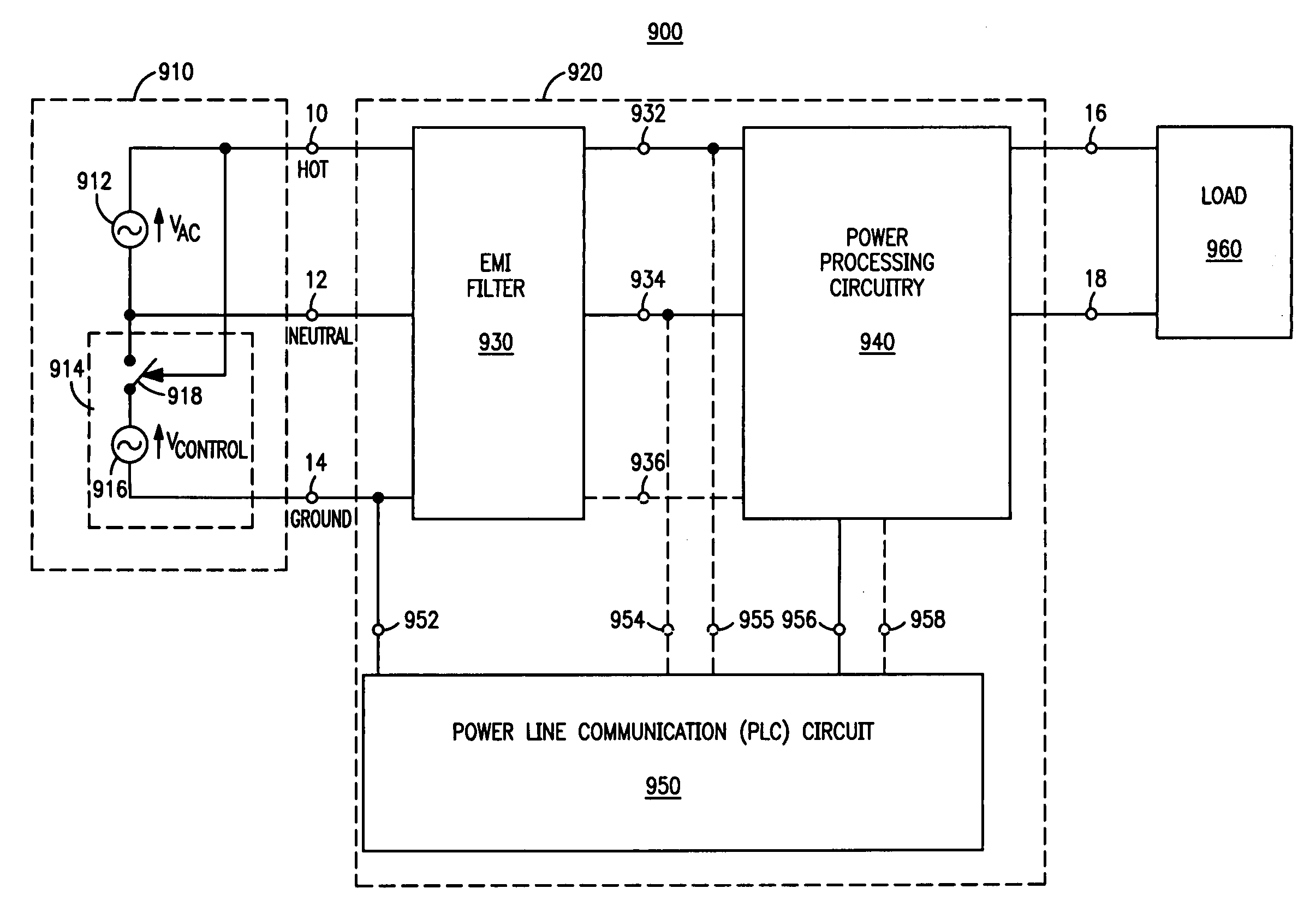
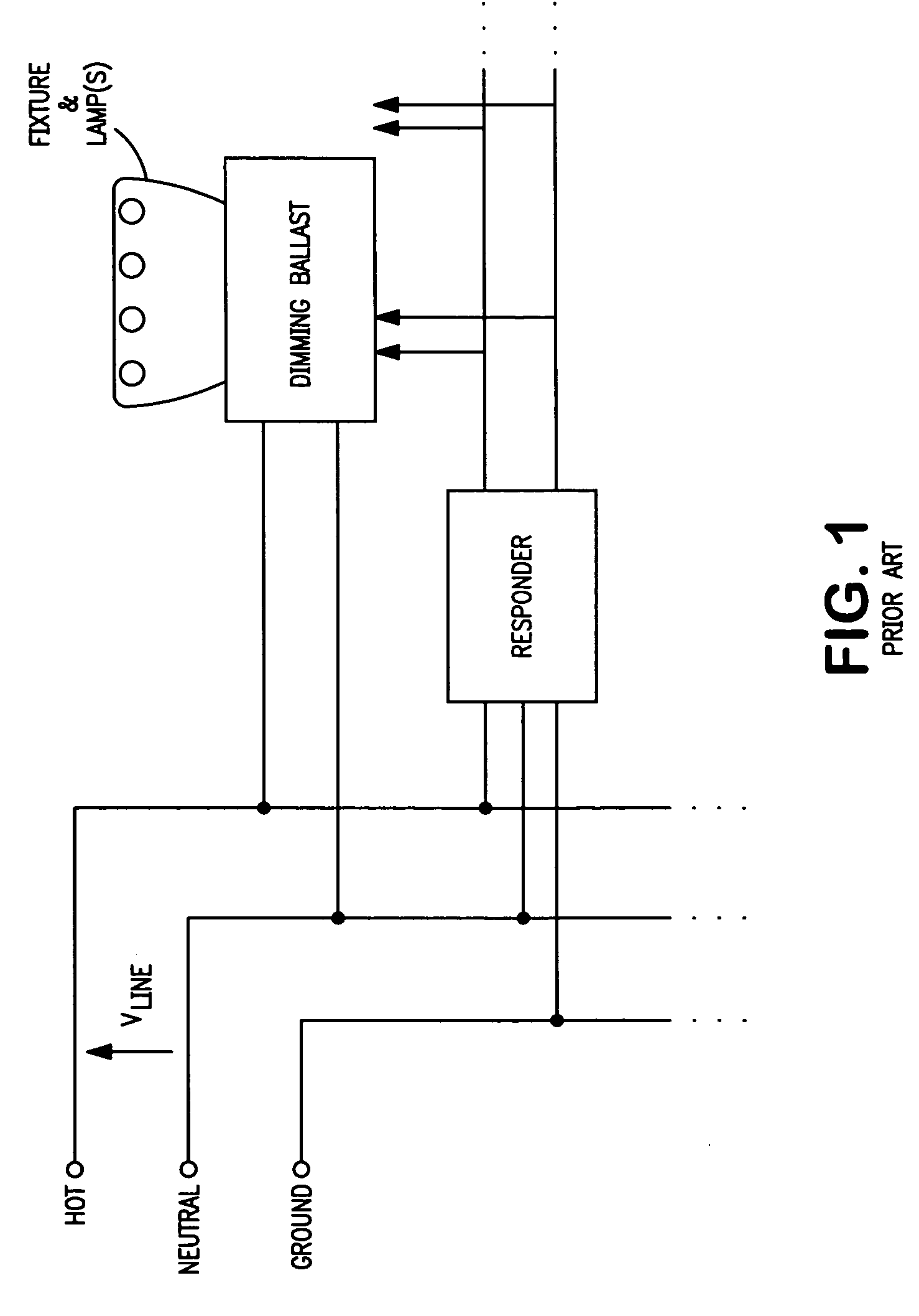
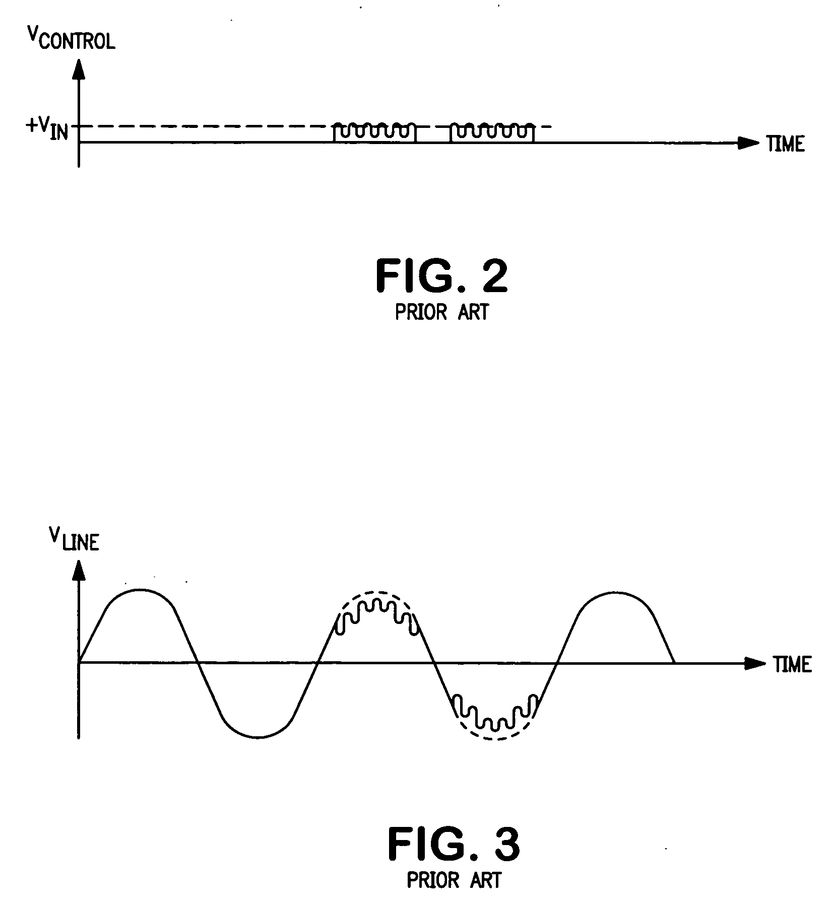
[0027] The present invention relates to power line communication (PLC) methods and circuits for use with power supplies and electronic ballasts. In particular, the present invention relates to PLC methods and circuits that provide one-way communication from an AC power source to a power supply or electronic ballast (i.e., without providing feedback messages from the power supply or ballast to a control station within the AC power source). The present invention is generally applicable to AC line powered power supplies or electronic ballasts for commercial, industrial, and / or residential wiring that utilizes neutral and ground connections, and in which the power supplies or ballasts include an electromagnetic interference (EMI) filter and, preferably, a power factor correction circuit.

[0028] Specific preferred embodiments of the present invention related to arrangements that include controllable (dimmable) electronic ballasts for powering gas discharge lamps. Specific applications of...


PUM


Abstract

An arrangement (900) and method (1000) for providing power line communication from an AC power source (910) to a circuit (900) for supplying power to a load (960), as well as electronic ballasts (20,30,40,70,80) that operate according to the method (1000). Method (1000) includes the steps of: providing (1010) an AC power source (910) that includes hot, neutral, and ground wires (10,12,14) and a control station (914) for generating a power line carrier control signal; providing (1020) a power supply circuit (920) having an EMI filter (930), power processing circuitry (940), and a power line communication (PLC) circuit (950); setting (1030) a fundamental frequency of the power line carrier control signal to be about equal to either an effective common-mode resonant frequency of the EMI filter (930) or a harmonic thereof; injecting (1040) a power line carrier control signal between the neutral and ground wires (12,14) of the AC power source (910); detecting (1050) the power line carrier control signal by monitoring a current flowing from the ground wire (14) to a circuit ground (90); and directing (1060) the power processing circuitry (940) to control load power in dependence on the detected power line carrier control signal. Specific preferred embodiments are directed to electronic ballasts (20,30,40,70,80) that include various PLC circuits (300,400,500,700).

Description

FIELD OF THE INVENTION [0001] The present invention relates to the general subject of power line communication. More particularly, the present invention relates to a power line communication arrangement and method that is well suited for use with power supplies and electronic ballasts that are, preferably, installed in buildings. BACKGROUND OF THE INVENTION [0002] Various power line communication (PLC) approaches are known in the art. Existing approaches for PLC control are basically carrier frequency based methods that utilize at least one high frequency carrier. For example: [0003] U.S. Pat. No. 4,538,136 (issued to Drabbing) teaches a two frequency keyed signal PLC system having a first predetermined frequency representing a first state of information (e.g., a “0”) and a second predetermined frequency representing a second state of information (e.g. a “1”). [0004] U.S. Pat. No. 6,377,163 (issued to Deller et al) teaches a PLC arrangement having a high frequency communication comp...

Claims


Application Information

Patent Timeline
Patent Type & Authority Applications(United States)
IPC IPC(8): H05B41/36
CPCH05B37/0263H05B47/185
Inventor ALEXANDROV, FELIX I.
Owner OSRAM SYLVANIA INC
Why Eureka
Try Eureka