Temperature-compensated piezoelectric oscillator

Active Publication Date: 2006-09-14
SEIKO EPSON CORP
View PDF2 Cites 11 Cited by
  • Summary
  • Abstract
  • Description
  • Claims
  • Application Information

AI Technical Summary

Benefits of technology

[0025] It is preferable that the control voltage in the low temperature be constant in the temperature above or at the common temperature, and that the control voltage in t

Problems solved by technology

However, since the frequency-temperature characteristic of crystal resonators are subject to fluctuation, the temperature compensation with the MOS capacitance deviation does not always result in an ideal compensation curve, and the precision of the temperature compensation is not high.
Therefore, the crystal resonators do not provide enough performance for the use of reference oscillators that require high stability in f

Method used


Image

  • Temperature-compensated piezoelectric oscillator
  • Temperature-compensated piezoelectric oscillator
  • Temperature-compensated piezoelectric oscillator

Examples


first embodiment

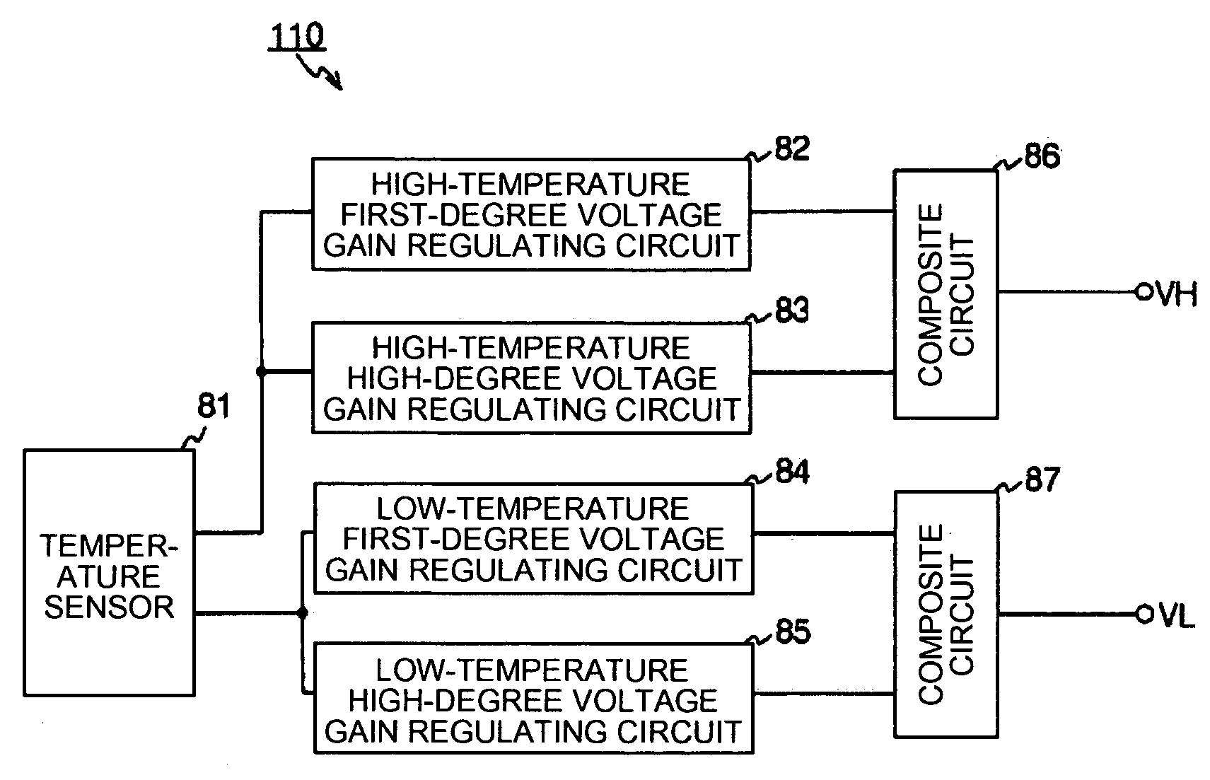
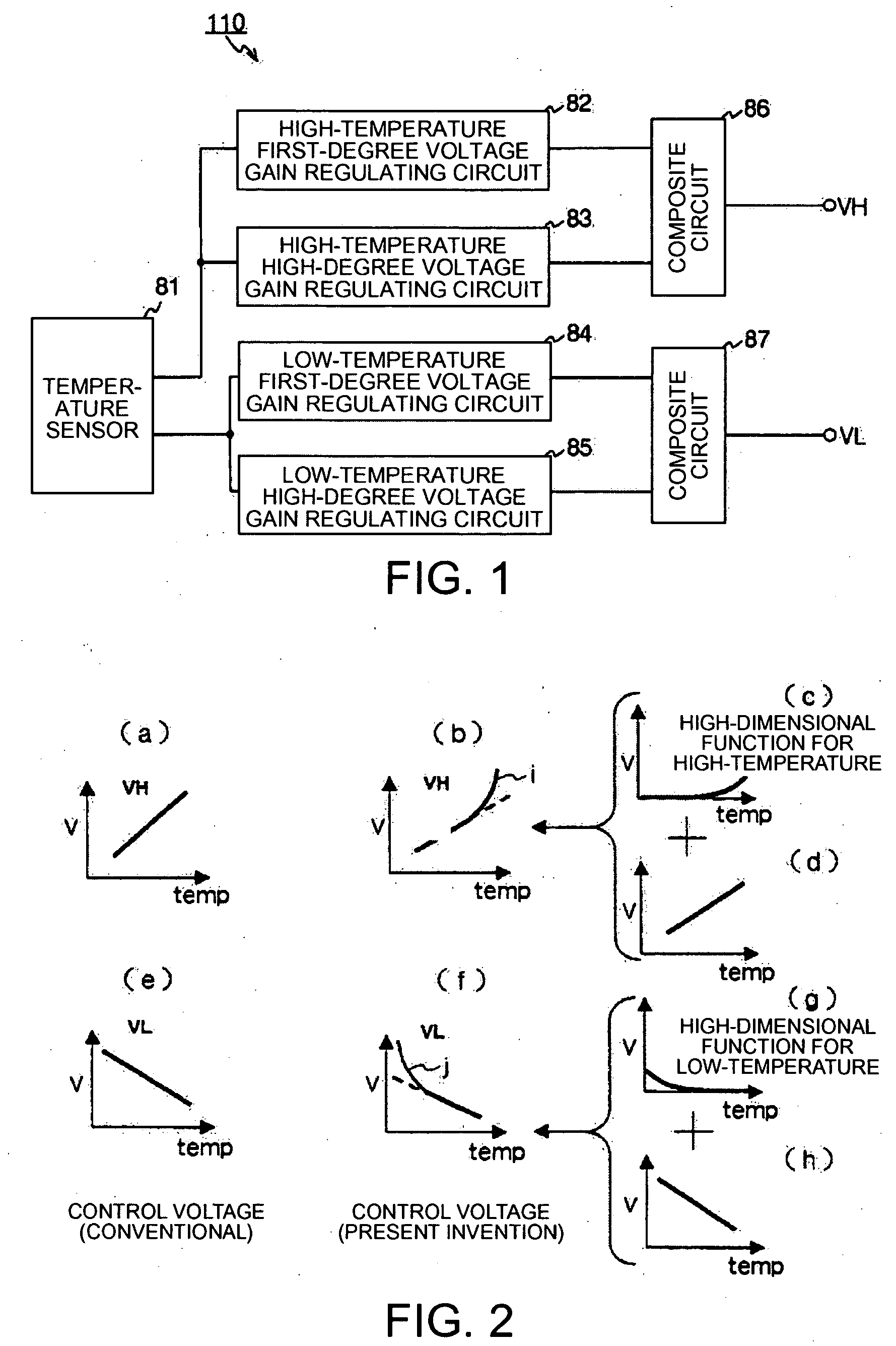
[0044]FIG. 1 is a block diagram of a function of a temperature-compensated voltage generation circuit that constitutes part of a temperature-compensated piezoelectric oscillator, according to the present invention. This temperature-compensated voltage generation circuit 110 includes: a temperature sensor (temperature detection unit) 81, where the parameter thereof changes with the surrounding temperature; a high-temperature first-degree voltage gain regulating circuit (high-temperature first-degree voltage generation circuit) 82 which generates a voltage that changes linearly with temperature; a high-temperature high-degree voltage gain regulation circuit (high-temperature high-degree voltage generation circuit) 83 that generates the voltage that behaves like a high degree function in a high temperature state of the voltage generated by this high-temperature first-degree voltage gain regulating circuit 82; a composite circuit (high-temperature voltage composite circuit) 86 that synt...

second embodiment

[0051]FIG. 4A is a block diagram of a modified function of a temperature-compensated voltage generation circuit that generates the compensation voltage supplied to the temperature-compensated piezoelectric oscillator that is in accordance with the invention. This temperature-compensated voltage generation circuit 100 includes: a temperature sensor (temperature detection unit) 1, where the parameter thereof changes with the surrounding temperature; a high-temperature first-degree voltage gain regulating circuit (high-temperature first-degree voltage generation circuit) 2 which generates a voltage that changes linearly with temperature; a high-temperature high-degree voltage gain regulating circuit (high-temperature high-degree voltage generation circuit) 3 that generates a voltage that behaves like a high degree function in a high temperature state of the voltage generated by the high-temperature first-degree voltage gain regulating circuit 2; the high-temperature first-degree voltag...

third embodiment

[0067]FIG. 6 is a block diagram of a function of a temperature-compensated voltage generation circuit that constitutes part of a temperature-compensated piezoelectric oscillator, according to the present invention. The temperature-compensated voltage generation circuit 200 includes: the temperature sensor (temperature detection unit) 21 that outputs electric signals that correspond to the change of the surrounding temperature; a first high-temperature first-degree voltage gain regulating circuit (first high-temperature first-degree voltage generation circuit) 24 that generates a voltage that changes linearly based on the temperature detecting information of the temperature sensor 21, so that the voltage is proportional to the temperature; a second high-temperature first-degree voltage gain regulating circuit (second high-temperature first-degree voltage generation circuit) 23 that generates a voltage that changes linearly in proportion to the temperature increase, based on the tempe...


PUM


Abstract

A temperature compensated piezoelectric oscillator includes: an oscillation circuit that drives a piezoelectric element with a current; a direct-current-stopping fixed capacitor; a frequency-temperature compensated circuit that compensates the deviation of an oscillation frequency caused by a change of temperature; and a piezoelectric transducer which includes a piezoelectric element driven in a prescribed frequency; where the above elements are connected serially.

Description

BACKGROUND [0001] 1. Technical Field [0002] The present invention relates to an oscillator that uses a piezoelectric element such as crystal, particularly to a temperature-compensated piezoelectric oscillator that allows temperature compensation of frequencies with a simple circuit configuration, and that is suitable for integrated circuits. [0003] 2. Related Art [0004] In recent years, the requirements for piezoelectric elements, for instance oscillators that use crystal resonators, have been increasingly demanded not only for frequency stability, but also for a lower price and smaller oscillators. Further, as the digitalization of communication system progresses, the improvement of carrier-to-noise ratio (C / N property) characteristics, which has not posed a problem in the past, is now sought after. Output frequencies of an oscillator changes with various causes. Even in crystal oscillators that have relatively higher stability in frequencies, there is a frequency deviation caused ...

Claims


Application Information

Patent Timeline
IPC IPC(8): H03L1/00
CPCH03B5/04H03B5/368H03L1/023H03L1/028H03B5/32H03L1/02
Inventor ISHIKAWA, MASAYUKIKIYOHARA, ATSUSHI
Owner SEIKO EPSON CORP
Why Eureka
Try Eureka