Operational bistatic radar system synchronization

a bistatic radar and synchronization technology, applied in the field of bistatic radars, can solve the problems of limiting the performance of bistatic radar for intended applications, prone to failure of data links, and inability to synchronize receive and transmit functions

Active Publication Date: 2006-09-14
RAYTHEON COMPANY INTPROP & LICENSING
View PDF11 Cites 28 Cited by
  • Summary
  • Abstract
  • Description
  • Claims
  • Application Information

AI Technical Summary

Benefits of technology

[0006] Above limitations are avoided by a bistatic radar of the present invention comprising a radar transmitter at a first location on a moving platform having a motion and a radar receiver at a second location, remote form the first location. The transmitter illuminates a target along an indirect path with an encoded radar signal. The target reflects the encoded radar signal to th

Problems solved by technology

There are two well known challenges in the design and operation of bistatic radars.
The other challenge is to minimize the direct path signal interference which may saturate and/or corrupt the indirect path signal containing target returns.
These two problems severely limit bistatic radar performance for intended applications, such as radar imaging and moving target detection.
Thu

Method used


Image

  • Operational bistatic radar system synchronization
  • Operational bistatic radar system synchronization
  • Operational bistatic radar system synchronization

Examples


Embodiment Construction

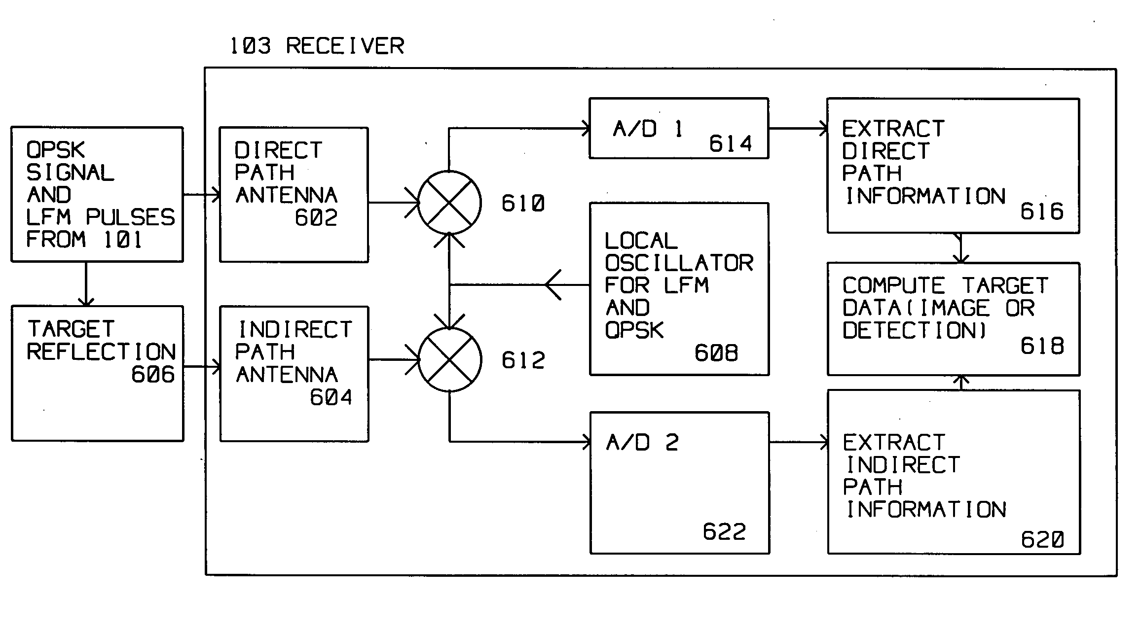
[0016] The present invention describes a method for synchronizing the receiver and transmitter (illuminator) in a bistatic radar. A high performance bistatic radar maintains overall bistatic system synchronization by:

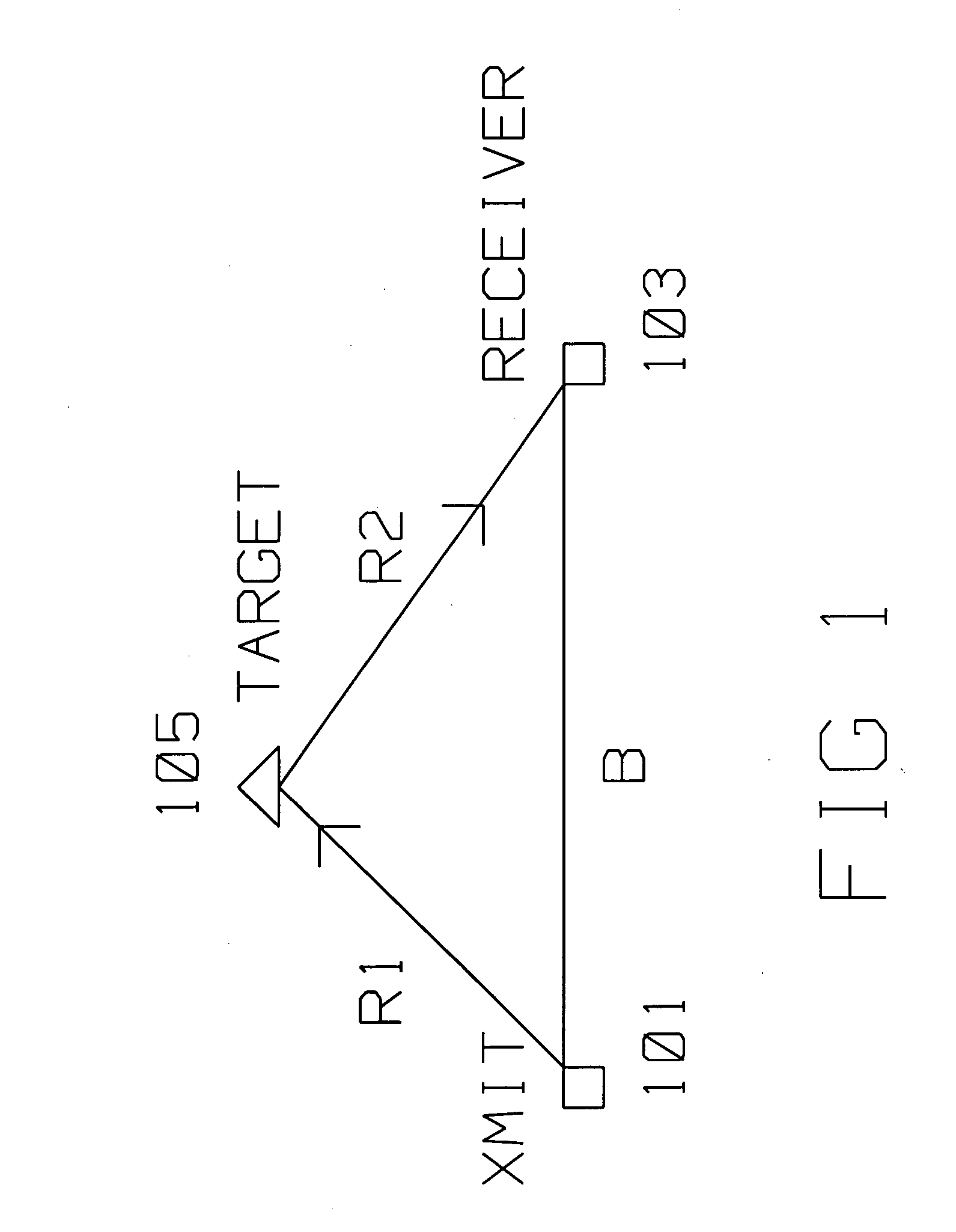
[0017] 1) Maintaining receiver window control over both the direct path (i.e. illuminator to receiver range and the indirect path (i.e. illuminator to ground to receiver containing the target information) so that autonomous bistatic operation is possible and interference from the direct path is avoided. These two windows are non-overlapped in time because of different path lengths. Direct path signal is used to provide phase reference signals to the indirect path signal thereby helping maintain the bistate phase coherency.

[0018] 2) Maintaining bistatic phase coherency between physically separated local oscillators (LOs), i.e. the illuminator LO and the one or more receiver LO to allow for coherent radar return processing. Bistatic phase coherence is maintained for eac...


PUM


Abstract

A bistatic radar has a radar transmitter at a first location on a moving platform having a motion and a radar receiver at a second location, remote from the first location. The transmitter illuminates a target along an indirect path with an encoded radar signal. The target reflects the encoded radar signal to the radar receiver. The transmitter concurrently provides the encoded radar signal to the radar receiver along a direct path. The encoded radar signal is radiated at a start time from a central reference point, and contains the first location, the pulse start time, the central reference point and the motion of the moving platform. Bit synchronization codes are also included. The radar receiver receives the encoded radar signal from the radar transmitter along the direct path during a first time interval, and the same encoded radar signal reflected from the target along the indirect path during a second time interval. The radar receiver decodes first information contained in the encoded radar signal from the direct path received during the first time interval to extract direct path information. The radar receiver also decodes second information contained in the encoded radar signal from the indirect path received during the second time interval to extract indirect path information. The radar receiver combines the direct path information and the indirect path information to to generate a target image or perform target detection. Linear Frequency Modulated (LFM) pulse coherency is maintained by extracting from the direct path pulse phase corrections and applying the phase correction to the indirect received LFM pulses.

Description

BACKGROUND OF THE INVENTION [0001] 1. Field of the Invention [0002] This invention is in the field of bistatic radars, specifically for the synchronization of radar pulses. [0003] 2. Description of the Related Art [0004] There are two well known challenges in the design and operation of bistatic radars. The first is to maintain bistatic phase coherency between the transmitter (illuminator) and the receiver. The other challenge is to minimize the direct path signal interference which may saturate and / or corrupt the indirect path signal containing target returns. These two problems severely limit bistatic radar performance for intended applications, such as radar imaging and moving target detection. [0005] Thus, a bistatic radar, because of the separation between the transmit portion (illuminator) and the receiver, is presented with the problem of synchronization of receive and transmit functions. That is, accurate phase information, transmit time, transmitter geo-location needs to be...

Claims


Application Information

Patent Timeline
IPC IPC(8): G01S13/00
CPCG01S13/003
Inventor CHEN, PILEIH
Owner RAYTHEON COMPANY INTPROP & LICENSING
Why Eureka
Try Eureka