
Intelligent modular server management system with enhanced graphical user interface

a server management system and modular technology, applied in the field of server management system, can solve the problems of reducing the quality of transmitted signals, requiring additional costs, and substantial wiring and wire harnessing, and achieve the effect of efficient selection, monitoring and control

Inactive Publication Date: 2006-09-14
RIIP
View PDF32 Cites 44 Cited by
  • Summary
  • Abstract
  • Description
  • Claims
  • Application Information

AI Technical Summary

Benefits of technology

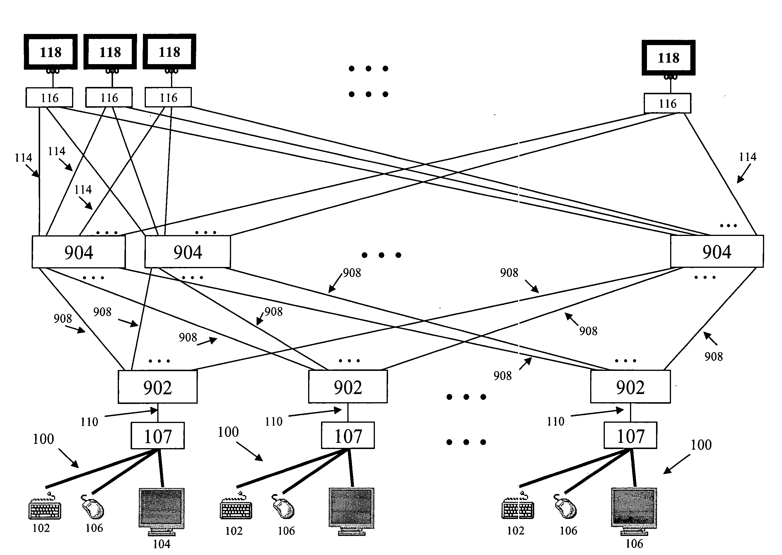
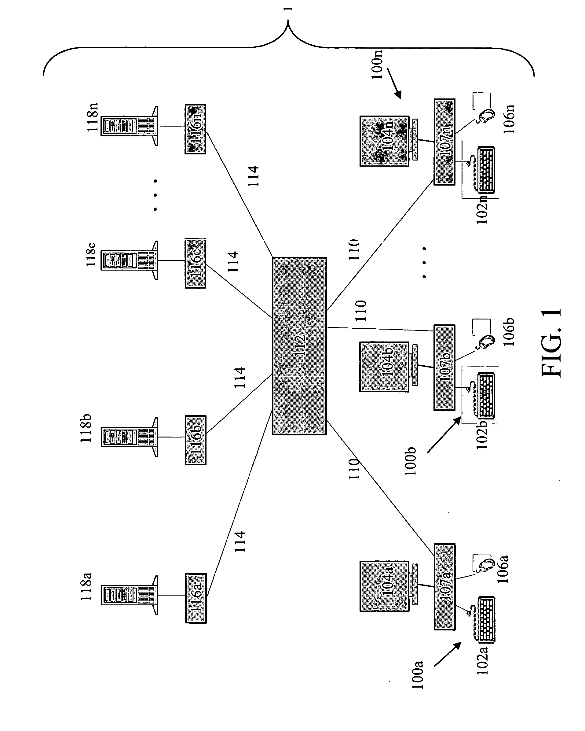
[0020] The present invention relates to a server management system for coupling a series of remote computers to one or more user workstations allowing for efficient selection, monitoring and control of the remote devices, servers or other devices. For example, in one configuration, the system of the present invention includes multiple computer interface modules (“CIMs”) each coupled to the keyboard, video, and cursor control device ports of a remote computer or server. Each CIM preferably communicates via cabling to a central matrix switching unit (“MSU”), and in turn the MSU communicates via cabling to user station devices (“USTs”). Each UST is coupled to a local keyboard, video monitor and cursor control device. The present invention displays video from a remote computer on the local monitor, and allows a user to remotely access and control a remote computer from a plurality of remote computers using the local keyboard and cursor control device.
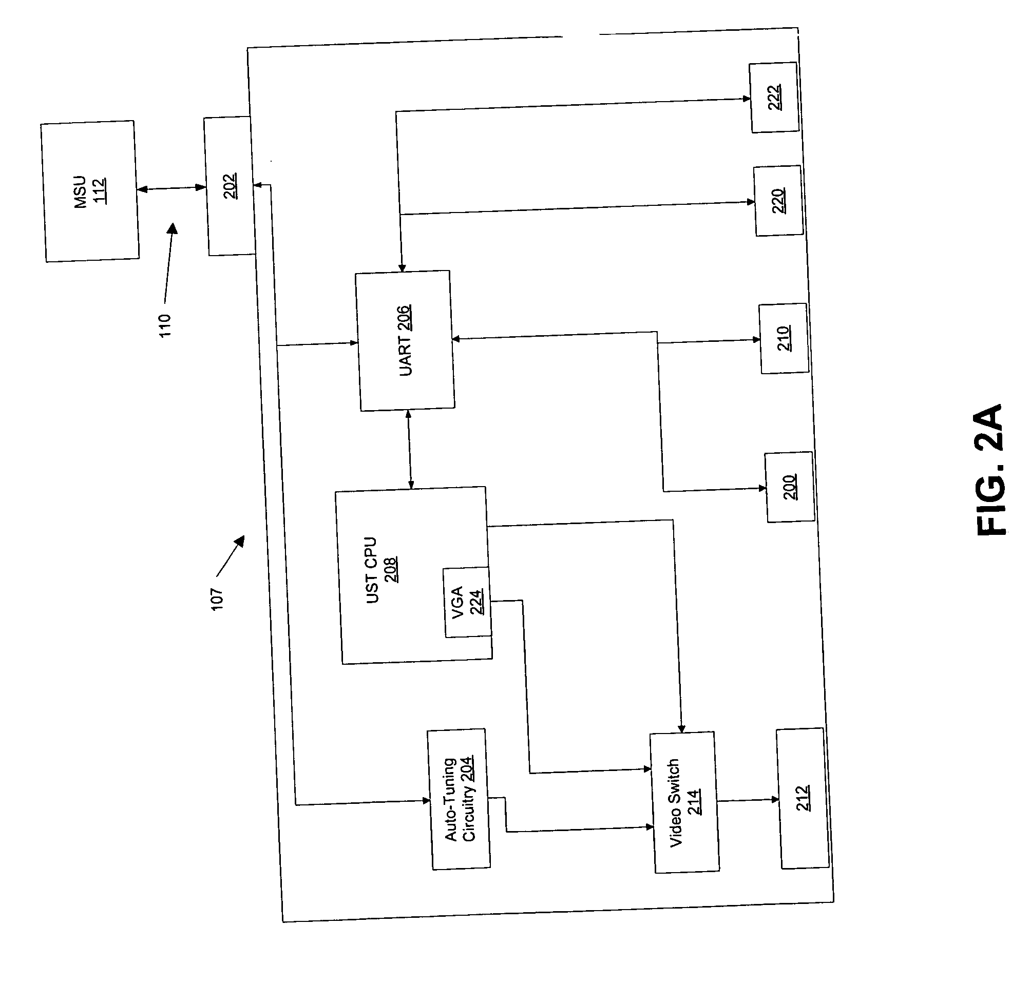
[0021] Preferably, the UST includes a general purpose central processing unit (CPU) that utilizes a standard operating system (e.g., Windows CE or Linux). Importantly, the general purpose CPU is used to perform the major control functions of the UST, including the display of an interactive GUI on the local video monitor to allow a user to view and select one of a plurality of remote devices. Having such a general purpose CPU generate the GUI has distinct advantages over the prior art. For example, it obviates the need for an on-screen display (OSD) processor, it enables the creation of a more user-friendly and intelligent interface, it has the ability to provide more information about servers than previous OSD chips, and the CPU can use existing operating systems (e.g., Windows CE, Linux, embedded Linux, etc.) to create an interface with a “look and feel” that is familiar to most users.

Problems solved by technology

However, such an alternative requires substantial wiring and wire harnessing, both of which may require additional cost.
Additionally, as the distance between the system administrator's user console and the remote computer equipment increases, a decrease in the quality of the transmitted signal often results.
Thus, dedicated cables between the system administrator's user console and remote computer equipment may not be a feasible alternative.
These environments typically require space to house a keyboard, video monitor, and mouse for each piece of computer equipment in addition to all of the wiring required to connect and power these components.
Furthermore, space is also required to house all of the network interface wiring.
As more equipment is added to a computer network, it becomes more probable that the space required for the equipment and associated cabling will exceed the space allotted for the network.
Therefore, network architecture, equipment size and available space are important issues when designing an effective computer network environment.
Elimination of this unnecessary equipment decreases the amount of space required for computer network environments.
However, solutions for selecting a remote computer that are known in the art present problems in large-scale computer operations.
For example, cycling through hundreds of computers utilizing only hot-keys can be time consuming and confusing for a user.
A simple list of remote computers is also prohibitive if a user must scroll through hundreds of choices to find the desired computer.

Method used


Image

  • Intelligent modular server management system with enhanced graphical user interface
  • Intelligent modular server management system with enhanced graphical user interface
  • Intelligent modular server management system with enhanced graphical user interface

Examples


Embodiment Construction

[0055] As required, a detailed illustrative embodiment of the present invention is disclosed herein. However, techniques, systems and operating structures in accordance with the present invention may be embodied in a wide variety of forms and modes, some of which may be quite different from those in the disclosed embodiment. Consequently, the specific structural and functional details disclosed herein are merely representative, yet in that regard, they are deemed to afford the best embodiment for purposes of disclosure and to provide a basis for the claims herein, which define the scope of the present invention. The following presents a detailed description of the preferred embodiment (as well as some alternative embodiments) of the present invention.

[0056] Referring first to FIG. 1, depicted is the architecture of the preferred computer management system in accordance with the present invention. Specifically, a modular, intelligent, computer management system is shown including a ...


PUM


Abstract

Disclosed is a remote computer or server management system for coupling a series of remote computers to one or more user workstations and providing an enhanced user interface for the selection, monitoring and control of a plurality of remote computers or servers by each workstation. Preferably, the user workstations include a keyboard, cursor control device, and video monitor through which a local user can select a remote computer for control through a central switch. The local workstation includes a general purpose processor programmed to display an enhanced graphical user interface (“GUI”) through which a local user can efficiently locate a remote computer for control. The GUI may also provide status indications for all servers, and may group the servers in an intelligent manner to aid the user in efficient location of the desired server.

Description

FIELD OF THE INVENTION [0001] The present invention relates to a server management system for coupling a series of remote computers to one or more user workstations where an enhanced graphical user interface (GUI) is presented on the video monitor of each user workstation. In particular, the user workstation includes a keyboard, cursor control device, video monitor, and a general purpose processor to produce a GUI that allows a user to view, select, monitor and control any one of the series of remote computers. BACKGROUND OF THE INVENTION [0002] A keyboard, video monitor, and mouse (“KVM”) switching system may be utilized to allow one or more user workstations to select and control any one of a plurality of remote computers via a central switching unit. Such systems are well known in the art and have been used by system administrators for at least ten years. Specifically, a KVM switching system allows a system user to control a remote computer using a local user workstation's keyboa...

Claims


Application Information

Patent Timeline
Patent Type & Authority Applications(United States)
IPC IPC(8): G09G5/00
CPCH04L12/24H04L12/403H04L41/00
Inventor LIAW, YEEHOERL, DAVIDHOLOVACS, JAYSON
Owner RIIP
Learn More