
Liquid crystal display, panel therefor, and manufacturing method thereof

a liquid crystal display and panel technology, applied in non-linear optics, instruments, optics, etc., can solve the problems of difficult adjustment of the amount of lc material to be filled in the gap between the panels, prone to deformation or damage of the spacer, and non-uniform distribution of lc, so as to facilitate the formation of the lc layer and maintain the cell gap uniform

Inactive Publication Date: 2006-09-14
CHO YOUNG JE +2
View PDF9 Cites 22 Cited by
  • Summary
  • Abstract
  • Description
  • Claims
  • Application Information

AI Technical Summary

Benefits of technology

[0010] It is a motivation of the present invention to keep the cell gap uniform and to facilitate the formation of the LC layer.
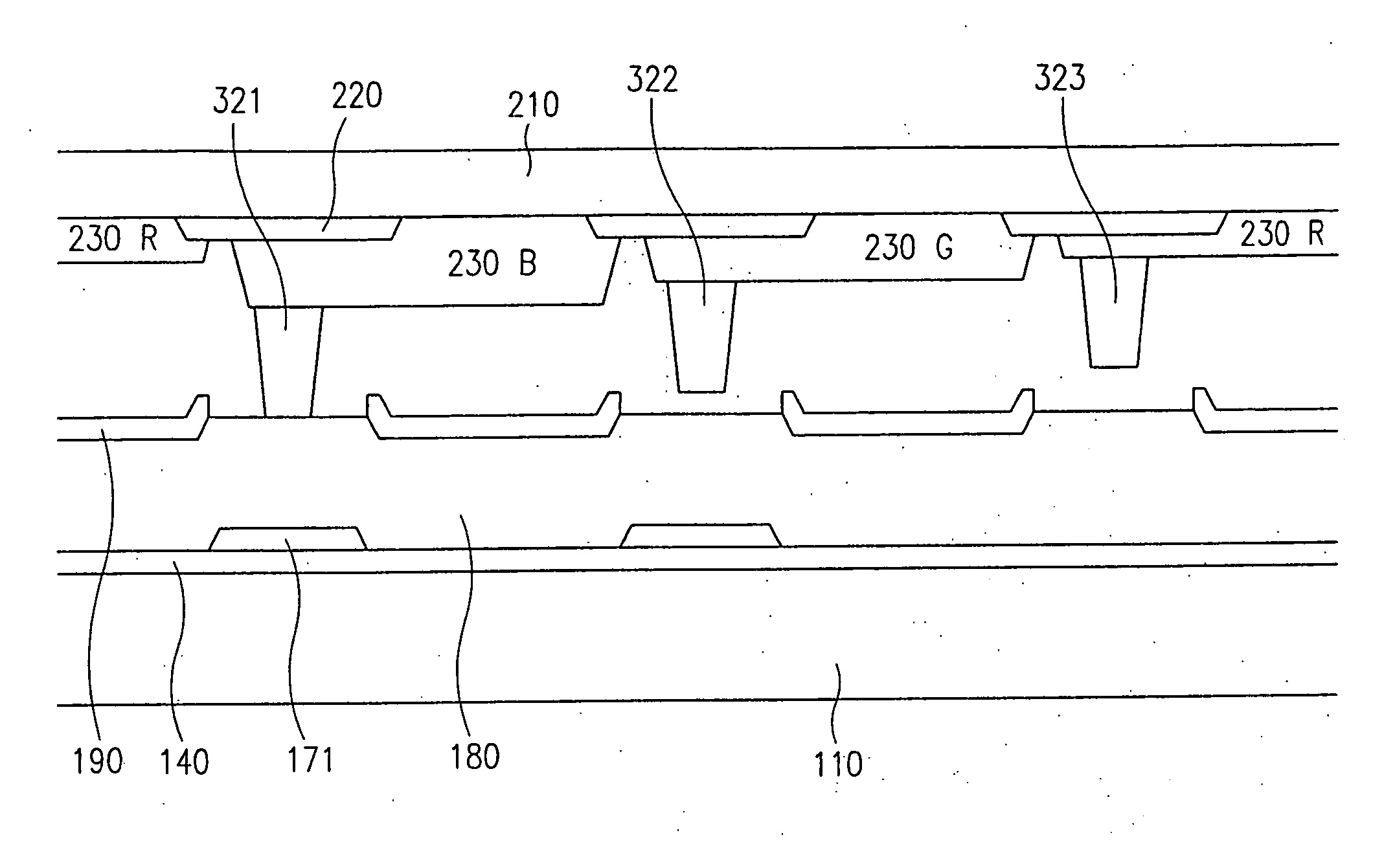
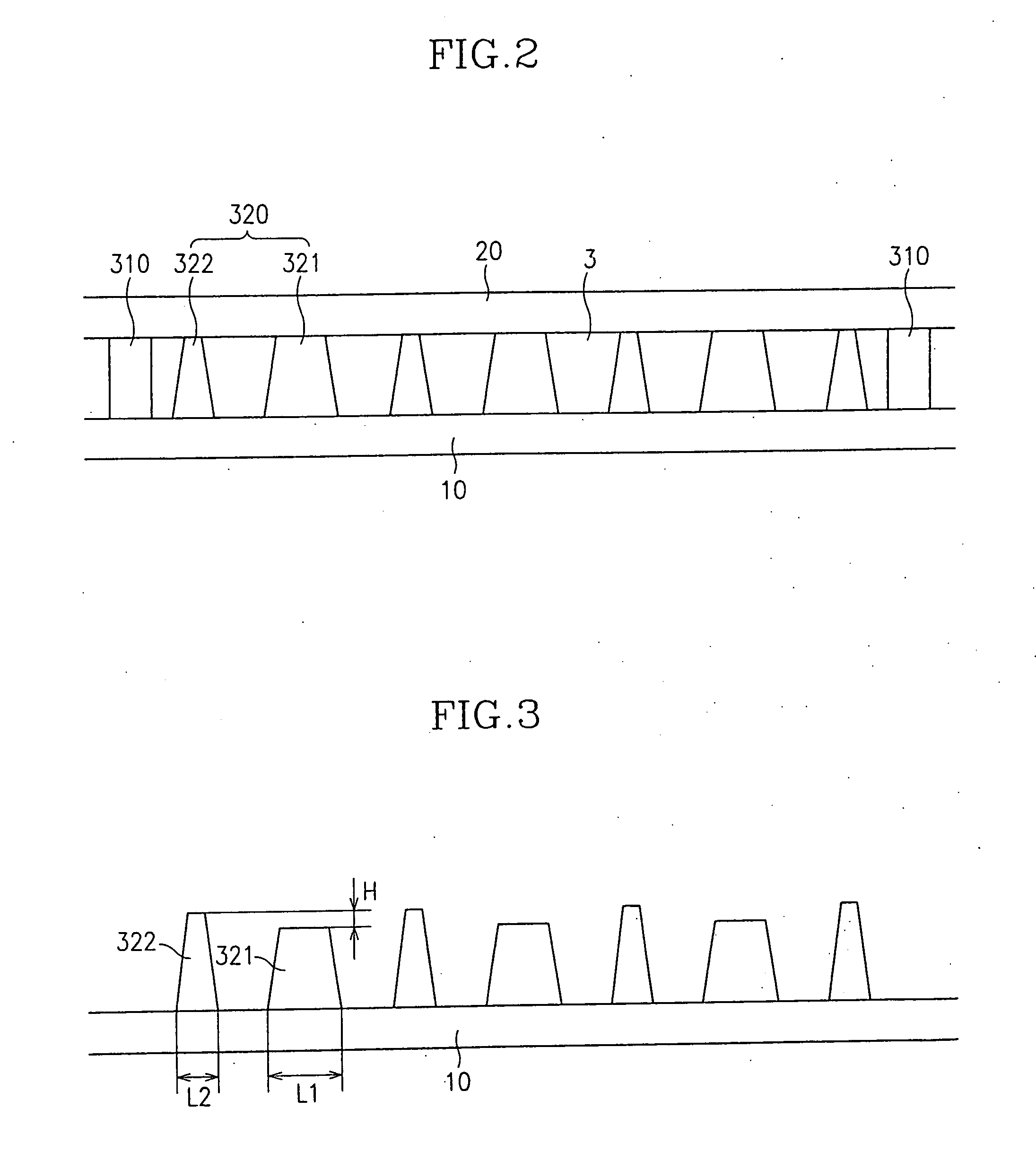
[0020] According to another embodiment of the present invention, a method of manufacturing a liquid crystal panel is provided, which includes: coating a photoresist on a panel; light-exposing the photoresist through an exposure mask including a plurality of transmissive areas having different transmittances and a blocking area; and developing the photoresist to form a plurality of spacers having different heights or different contact areas with the panel.

Problems solved by technology

When the cross sections of the spacers are too small to cause large compression deformation, the spacers are apt to be deformed or to be damaged.
On the contrary, if the cross sections of the spacers are too large to cause small compression deformation, it is difficult to adjusting the amount of the LC material to be filled in the gap between the panels.
The inappropriate amount of the LC causes bubbles or non-uniform distribution of the LC.

Method used


Image

  • Liquid crystal display, panel therefor, and manufacturing method thereof
  • Liquid crystal display, panel therefor, and manufacturing method thereof
  • Liquid crystal display, panel therefor, and manufacturing method thereof

Examples


Embodiment Construction

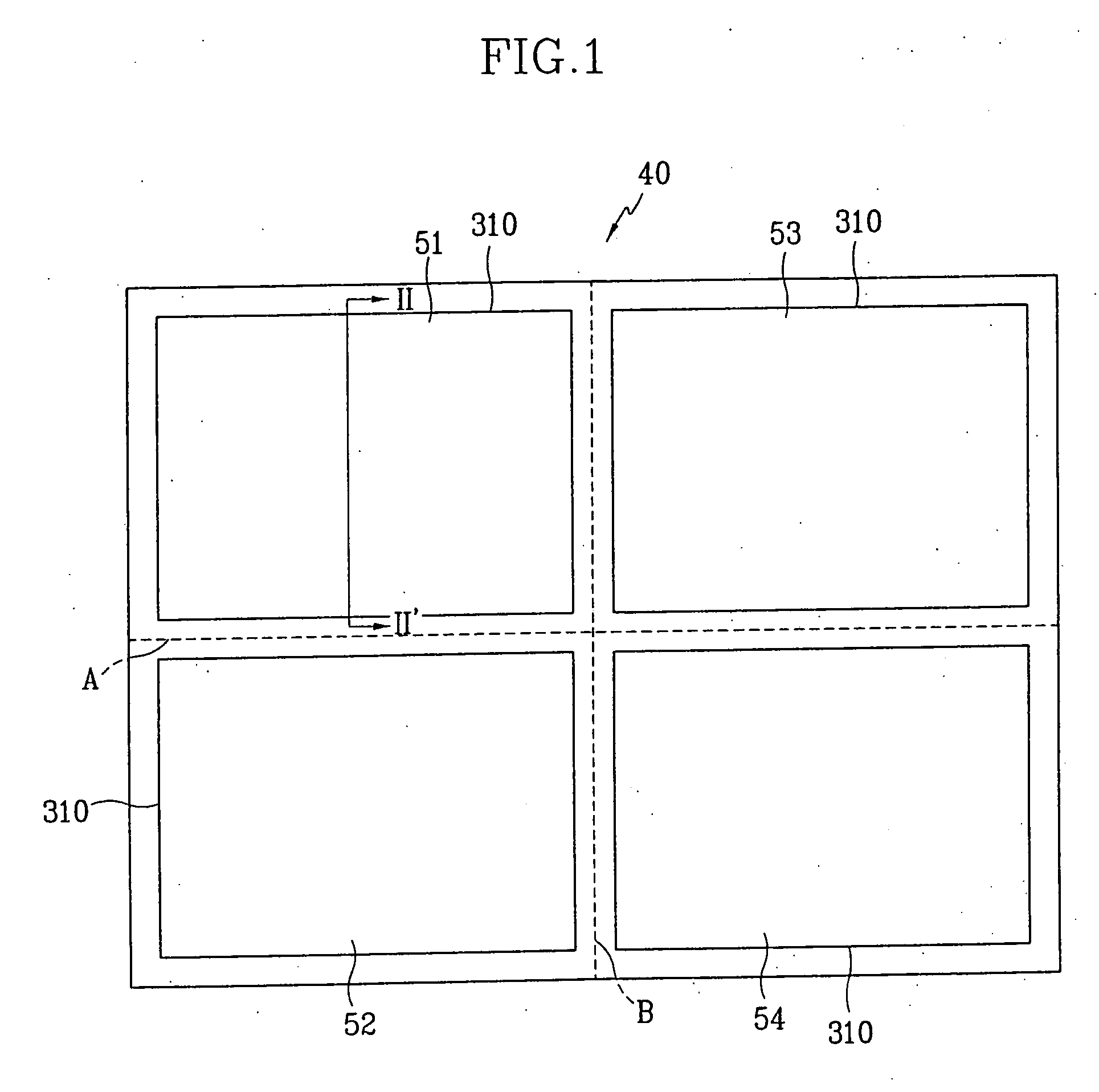
[0043] The present invention now will be described more fully hereinafter with reference to the accompanying drawings, in which preferred embodiments of the invention are shown. The present invention may, however, be embodied in many different forms and should not be construed as limited to the embodiments set forth herein.

[0044] In the drawings, the thickness of layers, films and regions are exaggerated for clarity. Like numerals refer to like elements throughout. It will be understood that when an element such as a layer, film, region or substrate is referred to as being “on” another element, it can be directly on the other element or intervening elements may also be present. In contrast, when an element is referred to as being “directly on” another element, there are no intervening elements present.

[0045] Now, liquid crystal displays, panels for a liquid crystal display, and manufacturing methods thereof according to embodiments of the present invention will be described with r...


PUM

PropertyMeasurementUnit
lengthaaaaaaaaaa
lengthaaaaaaaaaa
lengthaaaaaaaaaa

Abstract

A panel assembly for a liquid crystal display is provided. The panel assembly includes a panel and a plurality of spacers formed on the panel for supporting the panel. The spacers have at least two different heights or at least two different contact areas with the panel. The spacers include a plurality of first spacers and a plurality of second spacers having a height lower than the first spacers and having a contact area wider than the first spacers. The height difference between the first spacers and the second spacers is preferably in a range of about 0.3-0.6 microns, and the second spacers have a length larger than the first spacers preferably by 10-20 microns.

Description

CROSS-REFERENCE TO RELATED APPLICATION [0001] This application is a Divisional of U.S. application Ser. No. 10 / 672,304, filed on Sep. 26, 2003, the disclosure of which is hereby incorporated by reference herein in its entirety.BACKGROUND OF THE INVENTION [0002] (a) Field of the Invention [0003] The present invention relates to a panel for a liquid crystal display, a panel therefor, and a manufacturing method thereof, and in particular, to a liquid crystal display including spacers. [0004] (b) Description of Related Art [0005] Generally, a liquid crystal display (LCD) includes two panels including field-generating electrodes and coated with alignment layers and a liquid crystal (LC) layer having dielectric anisotropy and filled in a gap (called a cell gap) between the panels. Electric fields are applied to the LC layer by using field-generating electrodes and the transmittance of light passing through the panels are controlled by adjusting the field strength, thereby displaying desir...

Claims


Application Information

Patent Timeline
Patent Type & Authority Applications(United States)
IPC IPC(8): G02F1/1339G02F1/1335
CPCG02F1/133514G02F2001/13398G02F2001/13396G02F1/13394G02F1/13396G02F1/13398
Inventor CHO, YOUNG-JECHOI, WOOLEE, JEONG-HO
Owner CHO YOUNG JE
Learn More