Optical adjustment device, optical pickup apparatus provided with optical adjustment device, and method and apparatus for assembling optical adjustment device

a technology of optical adjustment device and optical pickup apparatus, which is applied in the manufacture of optical heads, optical head printing, instruments, etc., can solve the problems of device upsizing, complex structure, and larger spherical aberration as compared with objective lenses

Inactive Publication Date: 2006-09-14
SHARP KK
View PDF2 Cites 3 Cited by
  • Summary
  • Abstract
  • Description
  • Claims
  • Application Information

AI Technical Summary

Benefits of technology

[0064] According to the invention, the apparatus for assembling the optical adjustment device is provided with the pressing means that applies a pressing force within a predetermined range in the direction causing the connecting member to approach the screw-like member, to the precursor where the connecting member is placed across one of the first and second lens holders and the screw-like member, thereby resiliently deforming the connecting member, and the fixing means can fix the connecting member resiliently deformed by the pressing means, to one of the first and second lens holders in the resiliently deformed state. Consequently, it is possible to apply a predetermined pressing force in the direction approaching the screw-like member to the connecting member, thereby resiliently deforming the connecting member. Moreover, it is possible to maintain the abutting force of the connecting member and the screw-like member to be constant, and it is possible to provide an optical adjustment device that can maintain the fitting state of the connecting member and the screw-like member in a constant state.

Problems solved by technology

However, the spherical aberration of an objective lens gets larger in proportion to the fourth power of the NA of the objective lens and the thickness of an optical transparent layer of an optical recording medium, so that in a case where the NA of the objective lens is increased in order to reduce the spot diameter of a laser beam, there arises a problem that the spherical aberration gets larger as compared with that of an objective lens having a low NA.
Therefore, there is a problem that components count increases, the structure is complicated and the device is upsized.
In the second related art optical adjustment device, the knife edge is pressed against the feed screw by the spring and thereby fitted without fluctuation, and the lens holder can be displaced in the optical axis direction of the lens, but the device needs a plurality of guide rails, which causes increase of components count, complication of the structure and upsizing of the device.

Method used


Image

  • Optical adjustment device, optical pickup apparatus provided with optical adjustment device, and method and apparatus for assembling optical adjustment device
  • Optical adjustment device, optical pickup apparatus provided with optical adjustment device, and method and apparatus for assembling optical adjustment device
  • Optical adjustment device, optical pickup apparatus provided with optical adjustment device, and method and apparatus for assembling optical adjustment device

Examples


first embodiment

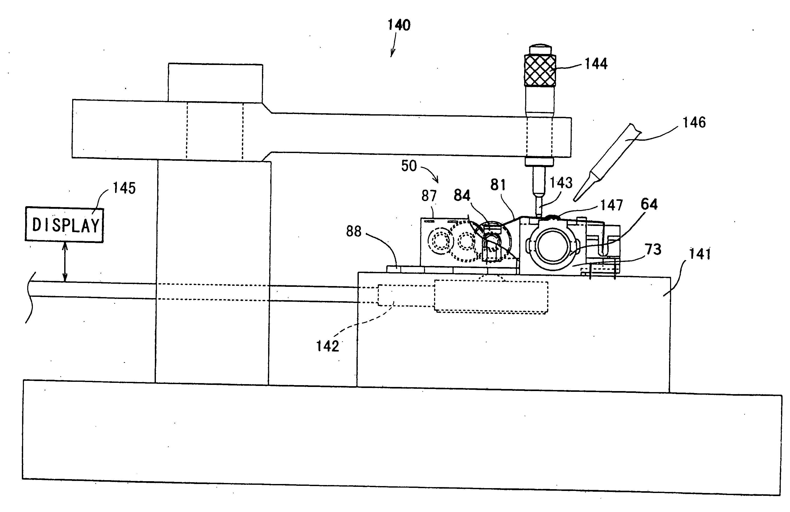
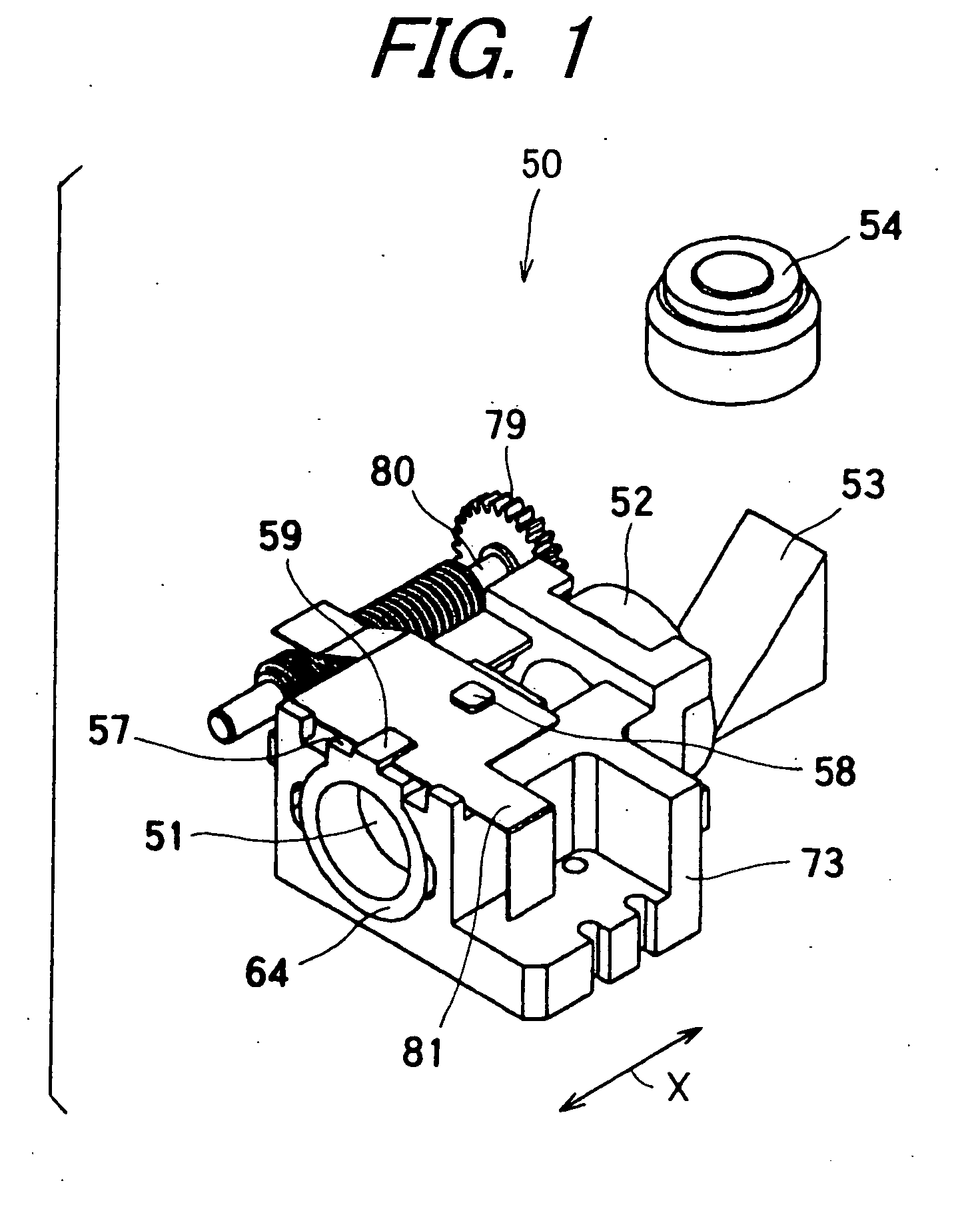
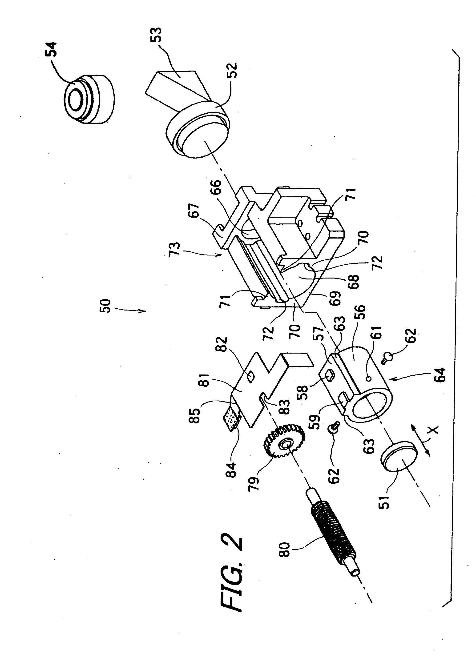
[0096]FIG. 1 is a perspective view showing an optical adjustment device 50 according to the invention. The optical adjustment device 50 is a device that adjusts spherical aberration caused by an error in thickness of an optical disk. The optical adjustment device 50 is disposed at a midway portion of a light path between a semiconductor laser device serving as a light source and an objective lens 54 that condenses light via a raising mirror 53. The optical adjustment device 50 has a concave lens 51 that is a second lens, a convex lens 52 that is a first lens formed in pairs (simply referred to as “convex lens” hereinafter), a second lens holder 64 that holds the concave lens 51, a first lens holder 73 that holds the convex lens 52, a feed screw member 80 serving as the screw-like member, a fourth reduction gear 79 that engages with the feed screw member 80, and a grip rack 81 serving as the connecting member.

[0097]FIG. 2 is an exploded perspective view showing the optical adjustment...

second embodiment

[0138] Although the present embodiment describes such a configuration that the opening portion 68b1 that is a sliding portion on the side of the first lend holder 73 abutting against the one circumferential end 63a of the second lens holder 64 is formed into a curved shape protruding to the other side in the Y-axis direction, that is, protruding toward the other circumferential end, the configuration will not be limited to the above one. In another embodiment of the invention, the opening portion 68b that is a sliding portion on the side of the first lend holder 73 abutting against the other circumferential end of the second lens holder 64 may be formed into a curved shape protruding to the one side in the Y-axis direction, that is, protruding toward the one circumferential end 63a. Also in this configuration, it is possible to obtain the same effect as in the

[0139] Further, it is also possible to configure so that an opening portion that is a sliding portion on the side of the firs...


PUM


Abstract

An optical adjustment device capable of correcting spherical aberration with high accuracy in a simple configuration is provided. A second lens holder fits into a guiding portion of a first lens holder, and a grip rack is placed across the second lens holder and a feed screw member and resiliently abuts against the feed screw member. The driving force of a driving source is transmitted to the grip rack via the feed screw member, and the grip rack is displaced. Therefore, it is possible to displace the second lens holder with respect to the first lens holder, and adjust the spherical aberration of an optical system.

Description

BACKGROUND OF THE INVENTION [0001] 1. Field of the Invention [0002] The present invention relates to an optical adjustment device which adjusts the spherical aberration of an optical system of an optical pickup apparatus, an optical pickup apparatus provided with the optical adjustment device, and a method and apparatus for assembling the optical adjustment device. [0003] 2. Description of the Related Art [0004] Although a magnetic recording method has been much used as a method for recording information, an optical recording method in which light is used for recording and reproducing information has come to be used in response to a demand for increase of information recording capacity. An optical recording medium is a recording medium which is of a large capacity and has an advantage of being rewritable and medium-exchangeable, and there are optical recording media based on a variety of standards, such as a compact disk (abbreviated to CD) and a family disk thereof, and a digital v...

Claims


Application Information

Patent Timeline
Patent Type & Authority Applications(United States)
IPC IPC(8): G03B27/42
CPCG11B7/22
Inventor NAKAMURA, MASAHIROSHITAMURA, HIRONOBU
Owner SHARP KK
Why Eureka
Try Eureka