Apparatus to detect a sync signal, a VSB receiver using the same, and a method thereof

a technology applied in the field of analog and digital signals can solve the problems of inability to detect sync signals accurately, phase noise influence cannot be removed, and the inability to detect sync signals

Active Publication Date: 2006-09-14
SAMSUNG ELECTRONICS CO LTD
View PDF5 Cites 67 Cited by
  • Summary
  • Abstract
  • Description
  • Claims
  • Application Information

AI Technical Summary

Benefits of technology

[0030] The predetermined number may be a number capable of excluding influence of a carrier frequency offset from the detected sync signal, and of keeping a correlation value between the training sequence and the received signal within a predetermined accuracy range.

Problems solved by technology

However, in the sync detection method described with reference to FIG. 1A, that uses the correlation of the “I” signal as the received real signal, the sync signal is detected using only the received real signal and therefore, influence by the phase noise cannot be removed.
In other words, in the sync detection method using the correlation of the received real signal (“I” signal), the sync signal is detected using only the “I” signal, and not using the “Q” signal and therefore, there is a drawback in that the sync signal with the phase noise is detected, thereby making it impossible to detect an accurate sync signal.
However, in the case where the phase noise and the carrier frequency offset both exist in the received signal, the sync signal cannot be detected accurately even in the sync detection method using the noncoherent correlation.
In other words, there is a drawback in that since the correlation value is varied by the carrier frequency offset, the sync signal cannot be accurately detected.
In the case where the frame synchronization is accurate, a sum of the square value of the correlation value of the “I” signal and the square value of the correlation value of the “Q” signal should be “1.” However, the sum of the respective square values does not become “1” due to the carrier frequency offset (f0) and therefore, the sync signal cannot be accurately detected.

Method used


Image

  • Apparatus to detect a sync signal, a VSB receiver using the same, and a method thereof
  • Apparatus to detect a sync signal, a VSB receiver using the same, and a method thereof
  • Apparatus to detect a sync signal, a VSB receiver using the same, and a method thereof

Examples


Embodiment Construction

[0043] Reference will now be made in detail to the embodiments of the present general inventive concept, examples of which are illustrated in the accompanying drawings, wherein like reference numerals refer to the like elements throughout. The embodiments are described below in order to explain the present general inventive concept by referring to the figures.

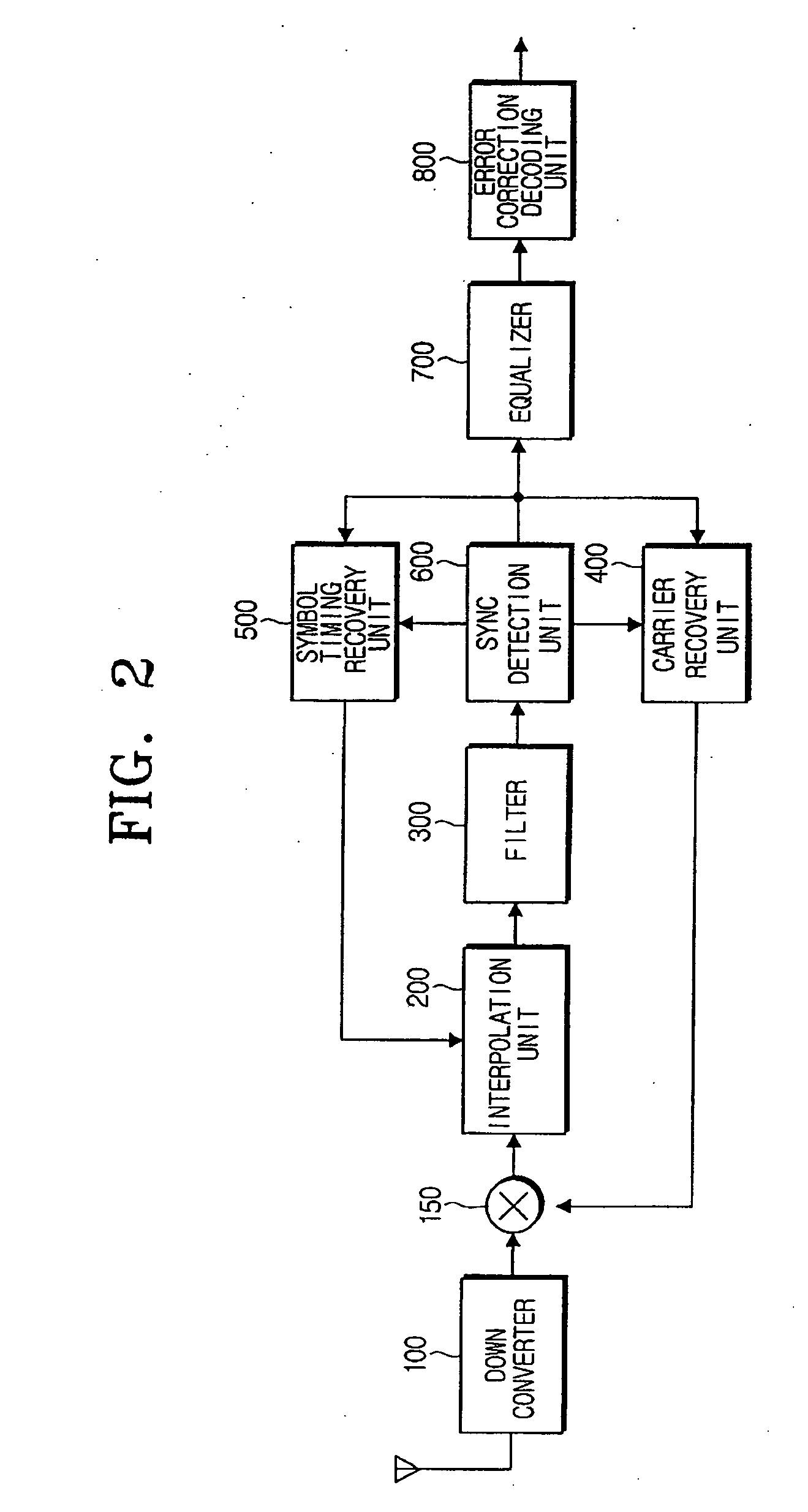
[0044]FIG. 2 is a block diagram illustrating a vestigial side band (VSB) receiver according to an embodiment of the present general inventive concept.

[0045] Referring to FIG. 2, the VSB receiver includes a down converter 100, a mixer 150, an interpolation unit 200, a filter 300, a carrier recovery unit 400, a symbol timing recovery unit 500, a sync detection unit 600, an equalizer 700, and an error correction decoding unit 800.

[0046] The down converter 100 receives a radio frequency (RF) signal through an antenna and converts the received RF signal into an intermediate frequency (IF) signal, and then again converts the IF si...


PUM


Abstract

An apparatus to detect a sync signal, a VSB receiver using the same, and a method thereof. The apparatus includes a plurality of partial correlators to calculate a first partial correlation value between a sub sequence of a training sequence and an “I” signal of a received signal that corresponds to a range of a sub sequence and a second partial correlation value between the sub sequence of the training sequence and a “Q” signal of the received signal, and calculating the first partial correlation value and the second partial correlation value for each of the predetermined number of sub sequences, a plurality of squarers to square the first and second partial correlation values for each sub sequence, respectively, a plurality of adders to add the squared first and second partial correlation values for each sub sequence and add the added squared partial correlation values of all the sub sequences to provide a correlation signal between the training sequence and a corresponding portion of the received signal, a maximum value detection unit to detect a maximum one of the added partial correlation values of the sub sequences from the correlation signal, and a position detection unit to detect a position of the detected maximum value as the sync signal of the received signal.

Description

CROSS-REFERENCE TO RELATED APPLICATIONS [0001] This application claims the benefit under 35 U.S.C. § 119(a) of Korean Patent Application No. 2005-20562, filed Mar. 11, 2005 in the Korean Intellectual Property Office, the entire contents of which are incorporated herein by reference. BACKGROUND OF THE INVENTION [0002] 1. Field of the Invention [0003] The present general inventive concept relates to an apparatus to detect a sync signal, a VSB receiver using the same, and a method thereof, and more particularly to an apparatus to detect a sync signal using a plurality of partial noncoherent correlators, a VSB receiver using the same, and a method thereof. [0004] 2. Description of the Related Art [0005] In a receiver for receiving data transmitted in a vestigial side band (VSB) modulation method, a frequency offset and a phase noise generated by a tuner or a radio frequency (RF) oscillator used in the receiver should be minimized in order to demodulate the data. This process is called “...

Claims


Application Information

Patent Timeline
Patent Type & Authority Applications(United States)
IPC IPC(8): H04L27/06H04L27/22
CPCH04L7/042B42D3/12B42F5/00
Inventor KWAK, JUNG-WONLEE, DONG-HOON
Owner SAMSUNG ELECTRONICS CO LTD
Why Eureka
Try Eureka