
Compact resilient anisotropic support for bearing

a resilient, bearing technology, applied in the direction of elastic bearings, rigid support of bearing units, machines/engines, etc., can solve the problems of compromising the performance of squeeze film dampers, bulky, expensive and/or difficult to retrofit to existing engines

Inactive Publication Date: 2006-09-14
HONEYWELL INT INC
View PDF21 Cites 61 Cited by
  • Summary
  • Abstract
  • Description
  • Claims
  • Application Information

AI Technical Summary

Benefits of technology

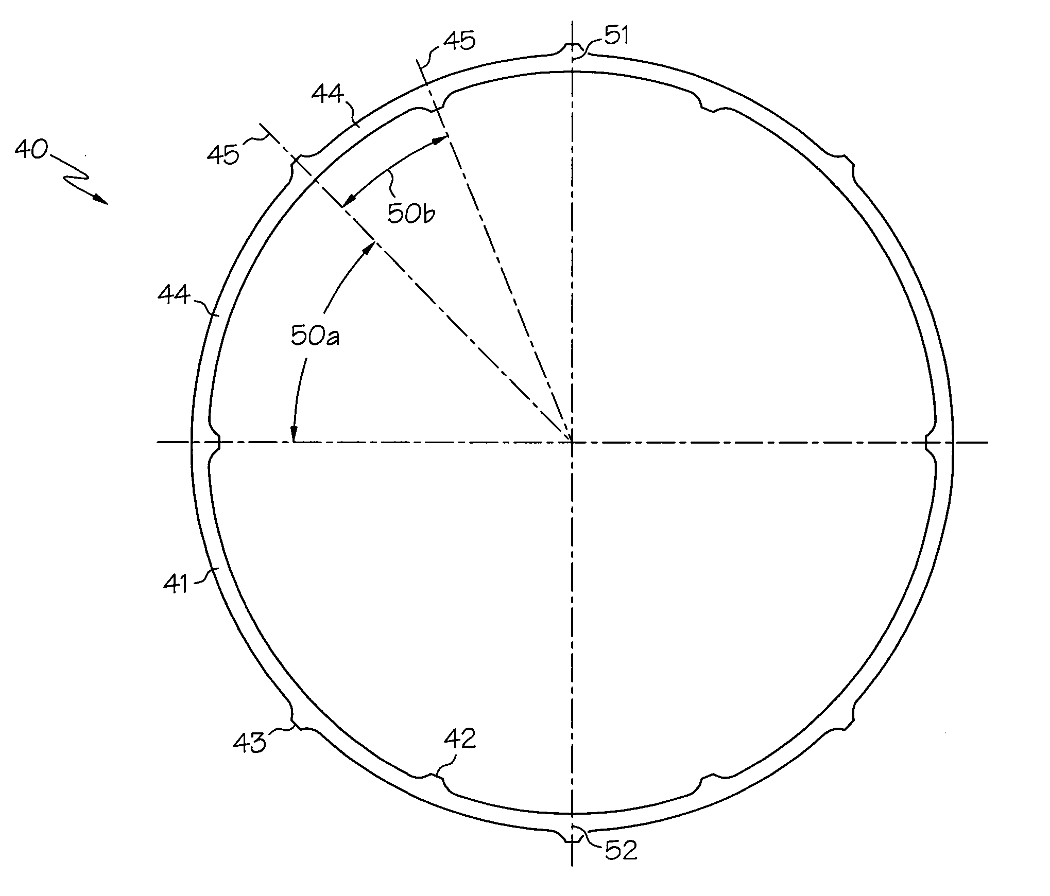
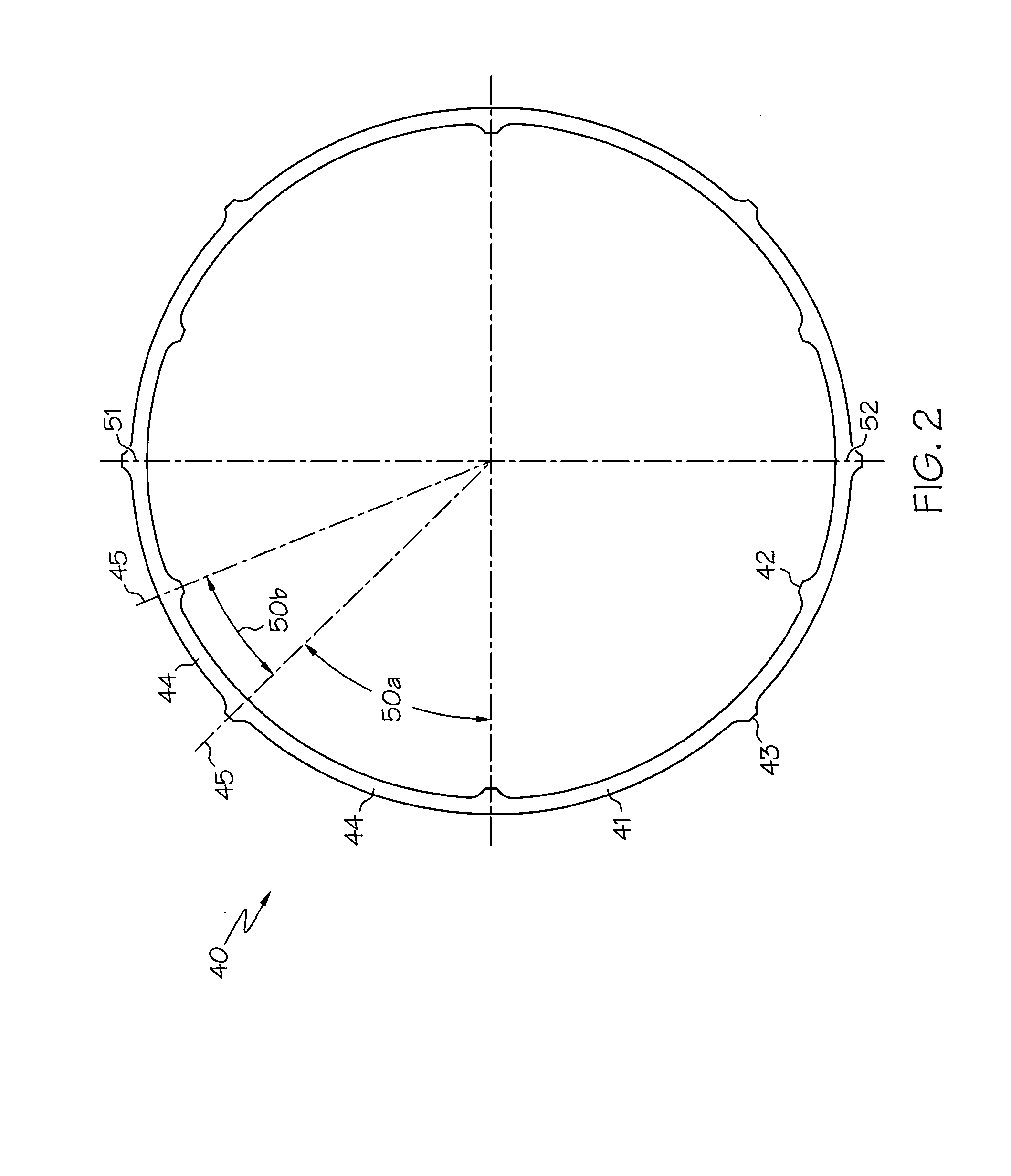
[0011] In still another aspect of the present invention, an apparatus for supporting a bearing assembly in an engine comprises an annular member radially outward from the bearing assembly; at least one inner bumper between the annular member and the bearing assembly; and at least one outer bumper radially outward from the annular member, the inner bumper and the outer bumper positioned to provide anisotropic stiffness to the annular member.
[0014] In a further aspect of the present invention, a method for rotatably supporting a rotor with a support housing comprises the steps of suspending the rotor from the support housing upon at least two bearing assemblies; centering the rotor with a bearing support assembly, wherein the bearing support assembly includes unevenly spaced inner and outer bumpers; and establishing a squeeze film damper between an outer race of the bearing assembly and the support housing.

Problems solved by technology

To counteract the tendency for the rotating assembly to operate off center, thus compromising the performance of the squeeze film damper, various conventional designs attempt to use a centering feature to maintain a uniform squeeze film damper thickness.
One such multi-component support comprises pivot supports and blocks and can only accommodate journal bearings.
Although the disclosed anisotropic supports can reduce non-synchronous vibration, they are bulky, expensive and / or difficult to retrofit to existing engines.

Method used


Image

  • Compact resilient anisotropic support for bearing
  • Compact resilient anisotropic support for bearing
  • Compact resilient anisotropic support for bearing

Examples


example 1

[0039] A bearing support assembly with anisotropic stiffness was compared to a support without aniostropic stiffness. As can be seen from a back to back engine test (FIGS. 6a-6c), the anisotropic support effectively controlled non-synchronous vibration (NSV) in the engine. The anisotropic support eliminated NSV and reduced synchronous vibration.

example 2

[0040] A compact compliant support, without anisotropy, was tested in another engine. The test data, shown in FIG. 7, shows the benefit of compliance to lower the vibration and shift down the critical speed. The present invention may combine the benefits of the compliant support with the benefits of the anisotropic support to create a compact light weight apparatus.

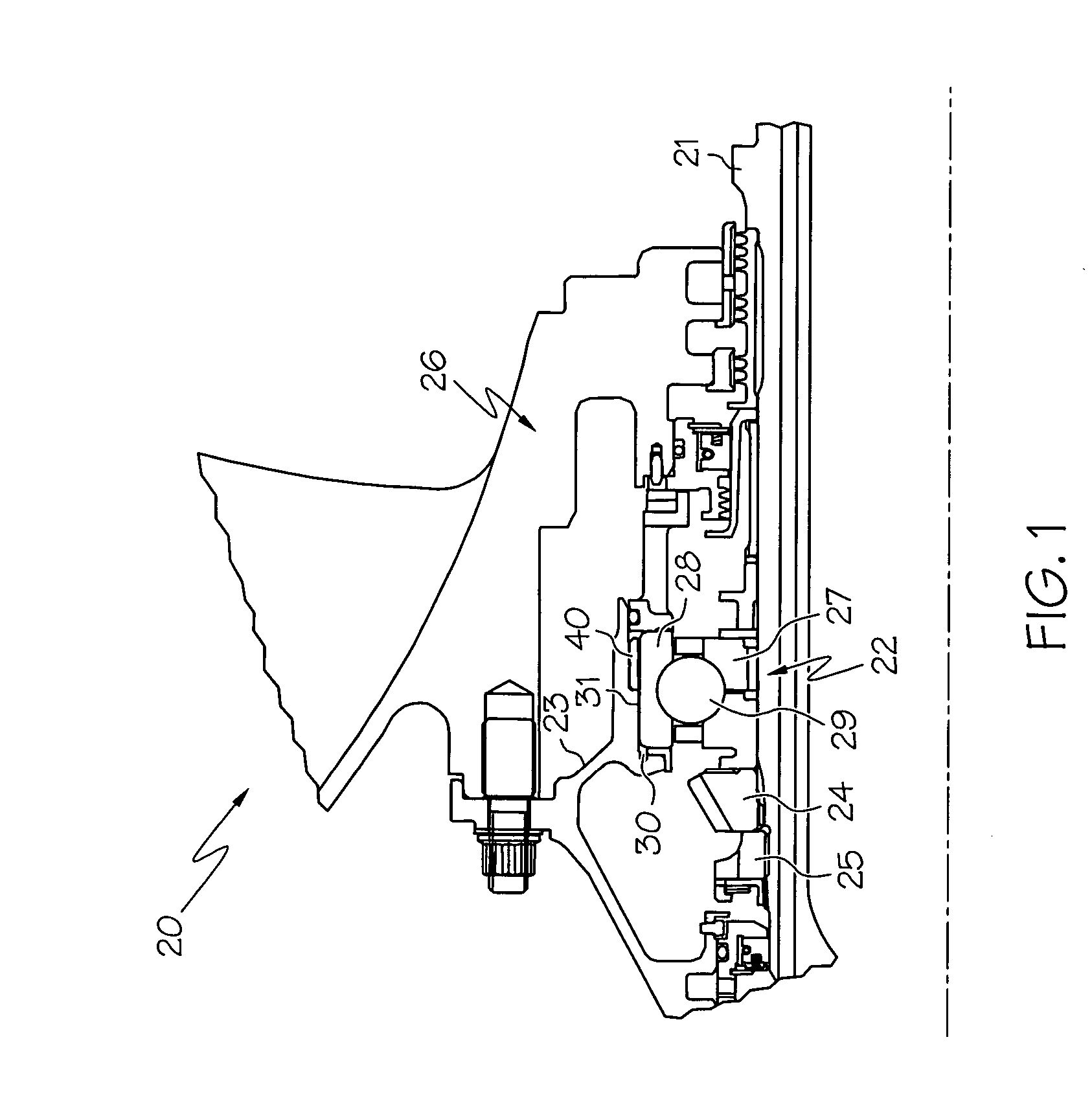
[0041] As can be appreciated by those skilled in the art, the present invention provides improved bearing support assemblies and methods for their production. The bearing support assemblies can lift the rotor inside the hydraulic mount cavity and eliminate rotor weight effect on the damper performance. The provided support assemblies can be offset in the vertical direction to center the rotor under 1g deflection to eliminate rub at the 6 o'clock location of a shroud. The outer bumper height can be controlled to limit maneuver deflection of the rotor. A compact, lightweight, and inexpensive apparatus is provided that can ...


PUM


Abstract

A support for a bearing comprises a resilient ring having unevenly spaced inner and outer bumpers. The unevenly spaced bumpers provide anisotropy to the rotor to preclude non-synchronous vibration. The inner bumpers can be ground to provide a vertical offset of the rotor centerline to accommodate the deflection due to the rotor weight. A tangential groove in the outer bumper allows oil passage during ring deflection so that oil can be squeezed out under dynamic load, providing additional viscous damping to the rotor.

Description

CROSS-REFERENCE TO RELATED APPLICATIONS [0001] This application is related to co-pending and commonly assigned U.S. patent application Ser. No. 10 / 967,979, filed Oct. 19, 2004, entitled “Compact Compliant Centering Support for Squeeze Film Damper”, which is incorporated by reference herein.BACKGROUND OF THE INVENTION [0002] The present invention generally relates to gas turbine engines and, more particularly, to bearing support assemblies that interface between the bearing assemblies and the support housing of the gas turbine engine. [0003] The gas turbine engine may include rotating components such as a fan, a compressor, and a turbine. The rotating components may be clamped either by a tieshaft or bolted flange joints to form a rotor group. Two or more bearing assemblies may support the rotor group. The bearing assemblies may be surrounded by the support housing, which may be connected to an engine case. During high-speed rotation of the rotor group, forces may be transmitted from...

Claims


Application Information

Patent Timeline
Patent Type & Authority Applications(United States)
IPC IPC(8): F16C27/00
CPCF01D25/164F05B2230/606F16C27/045F16C19/06F05D2230/642F16C2360/23
Inventor ALAM, MOHSIULSPENCER, DOUG K.
Owner HONEYWELL INT INC
Learn More