Switched multiplexer method to combine multiple broadband RF sources

a multiplexer and broadband rf technology, applied in the field of unique configuration of switched multiplexers, can solve the problems of system df capability errors, secondary and third harmonic filtering cannot be performed by a fixed filter, etc., to avoid 3 db or more loss, reduce reflection, and reduce the effect of reflection

Active Publication Date: 2006-09-14
NORTHROP GRUMMAN SYST CORP
View PDF15 Cites 18 Cited by
  • Summary
  • Abstract
  • Description
  • Claims
  • Application Information

AI Technical Summary

Benefits of technology

[0015] The transmitter and / or the transmit switch may control or direct the transmit signal to the appropriate one of the first, second, third and fourth switches. Remaining ones of the first, second, third and fourth switches which are not selected by the transmit switch terminate their input signal into a resistive load. By including the resistive termination with at least three of the first, second, third and fourth switches, a stable output impedance is provided across the frequency band which is conveyed by the particular one of the signal path's filter (e.g., 2.0-3.5 GHz) as may be seen from the point of view of the output pin. More specifically, each one of the first, second, third and fourth filters are either presented with a good 50-ohm termination or an actual 50-ohm resistance is included with the transmitter itself. Such resistive termination stabilizes each one of the first, second, third and fourth filter's output impedance which therefore stabilizes the switched multiplexer output impedance.
[0017] The first diplexer and the second diplexer combine standard frequency bands with minimal loss (e.g., <1 dB) to respective ones of the first, second, third and fourth filters' pass band. Such an arrangement avoids a 3 dB or more loss associated with a broadband combiner. Furthermore, the arrangement of the first and second diplexers avoids the disturbance of filter impedances in the rejection band (i.e., out of the pass band). Both of the signal paths which combine to form each of the first and second diplexers have non-adjacent frequency ranges (e.g., 2-3.5 GHz and 6-10.4 GHz) such that a “gap” (e.g., 3.5-6 GHz) is created, allowing a realizable diplexer to be designed with a crossover point (e.g., 4 GHz) that is within the “gap”.

Problems solved by technology

In multi-octave systems, such filtering of secondary and third harmonics cannot be performed by a fixed filter.
Unfortunately, the use of an 18 GHz filter would also passage of the second harmonic from the transmitter when operating in the range of from about 2-9 GHz.
Unfortunately, switches such as those used in FIG. 1, (i.e., the single-pole-quadruple-throw [1P4T]) switch and the single-pole-quintuple-throw [1P5T] switch) are typically reflective.
In a multi-channel combining network, the changing output impedance will result in phase and amplitude errors in the signal each time the switch (e.g., the 1P5T switch of FIG. 1) changes which unfortunately results in errors in the DF capability of a system.

Method used


Image

  • Switched multiplexer method to combine multiple broadband RF sources
  • Switched multiplexer method to combine multiple broadband RF sources
  • Switched multiplexer method to combine multiple broadband RF sources

Examples


Embodiment Construction

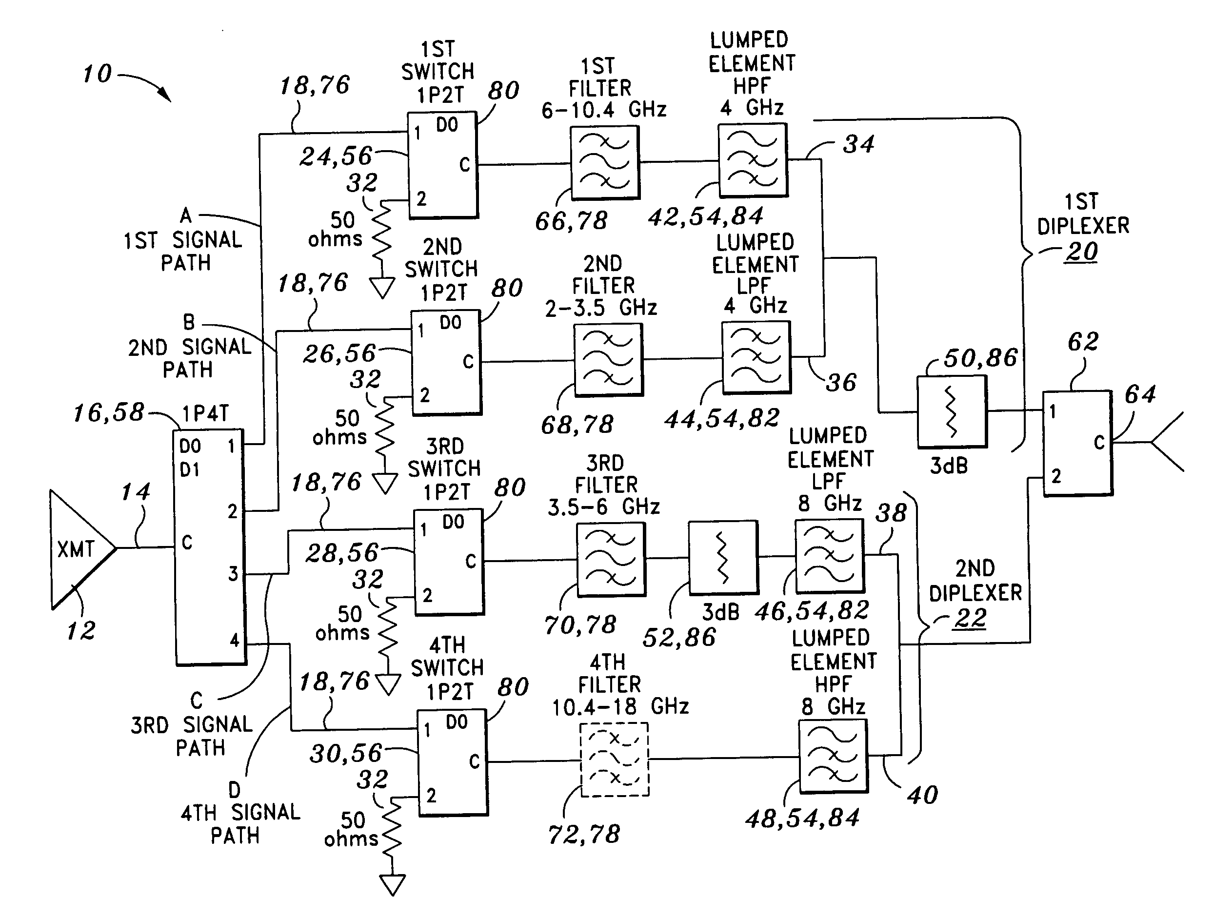
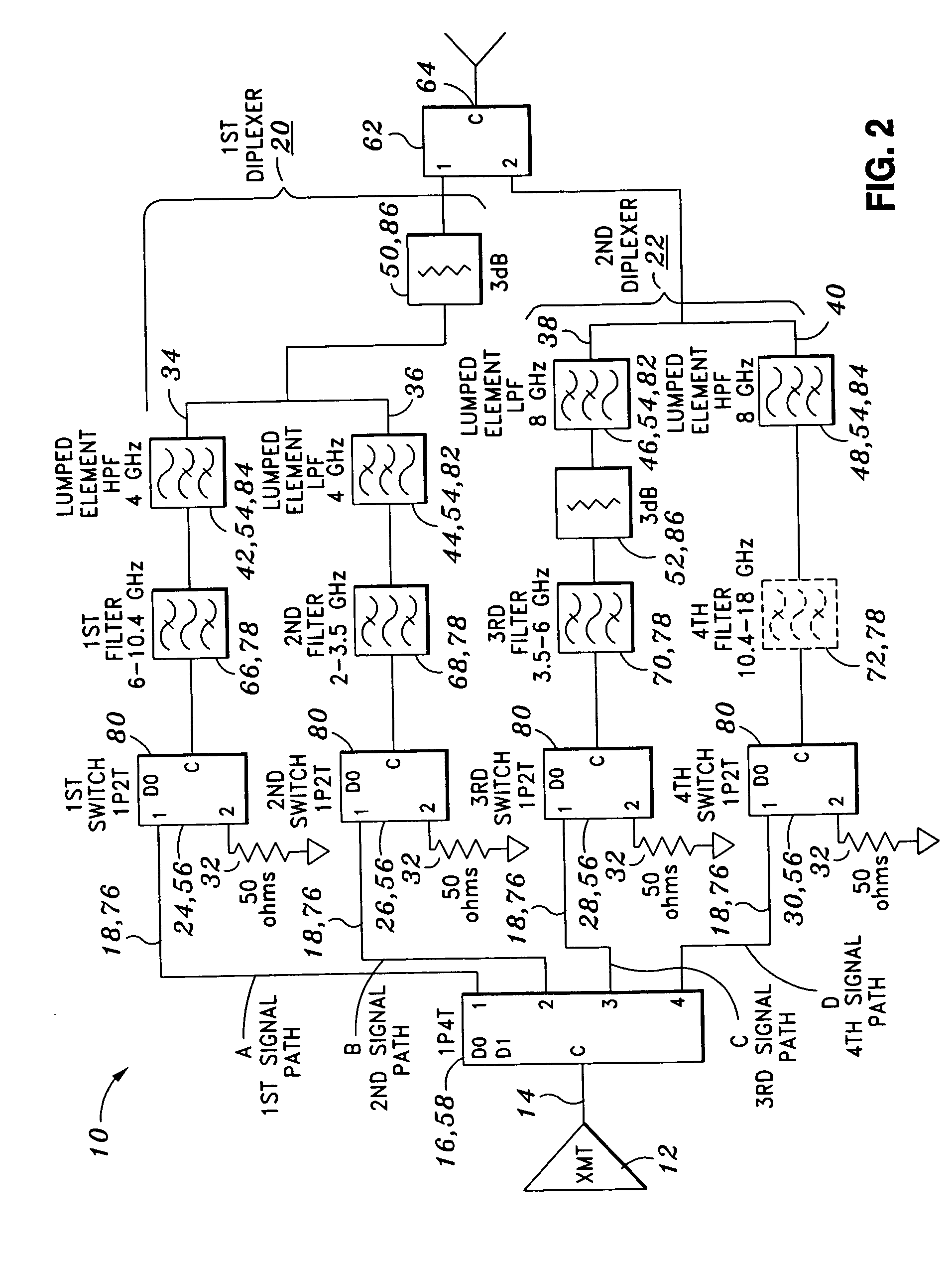
[0024] Referring now to the drawings wherein the showings are for purposes of illustrating the present invention and not for purposes of limiting the same, provided is a uniquely configured switched multiplexer 10 configured to operate in a frequency range of from fmin to fmax and to remove transmitter 12 harmonics of an input signal 14 to thereby create a stable output impedance across the frequency range.

[0025] In its broadest sense, the switched multiplexer 10 comprises a transmit switch 16, a bank of diplexers connected in parallel with one another, and a power combiner 62 connected to the bank of diplexers. The switched multiplexer 10 is specifically configured to combine a quantity of signal paths 76 each covering a sub-octave in the frequency range of from fmin to fmax. The low end of the frequency range is represented by fmin. The upper end of the frequency range is represented by fmax. The switched multiplexer 10 is configured to remove transmitter 12 harmonics of a known ...


PUM


Abstract

Provided is a switched multiplexer configured to combine first, second, third and fourth signal paths each covering a sub-octave in a frequency range of from about 2 to about 18 GHz and to remove transmitter harmonics of an input signal to create a stable output impedance across the frequency range. The switched multiplexer comprises a transmit switch, a first diplexer and a power combiner. The first diplexer is connected in parallel with a second diplexer. The first diplexer comprises first and second signal paths. The second diplexer comprises third and fourth signal paths. Each one of the first, second and third signal paths include respective ones of the first switch, a second switch and a third switch, each interconnected to respective ones of a first signal path high-pass filter, second signal path low-pass filter and third signal path low-pass filter by respective ones of a first, second and third filter. Each one of the first, second and third filters have a respective filter capability in the range of from about 6-10.4 GHz, 2-3.5 GHz, and 3.5-6 GHz.

Description

STATEMENT RE: FEDERALLY SPONSORED RESEARCH / DEVELOPMENT [0001] The present invention was developed under U.S. Government Contract No. 131980. Accordingly, the United States Government may have certain rights in the present invention.CROSS-REFERENCE TO RELATED APPLICATIONS [0002] (Not Applicable) BACKGROUND OF THE INVENTION [0003] The present invention relates generally to radio frequency (RF) signal processing and, more particularly, to a uniquely configured switched multiplexer that uses a bank of filters to filter a signal generated by a multi-octave transmitter whose frequency may vary over time. The switched multiplexer is also adapted to create a stable output impedance regardless of which one of the filters among the bank is selected, across the entire frequency range (e.g., 2-18 GHz) in order to reduce the phase and amplitude error of the signal. [0004] In the field of RF signal processing, multi-octave transmitters are used wherein it is necessary to filter off transmitter ha...

Claims


Application Information

Patent Timeline
Patent Type & Authority Applications(United States)
IPC IPC(8): H04B15/00
CPCH04B1/44H04B15/00
Inventor BIALEK, EDWARD J.HEIMBUEGER, JAMES J.IRWIN, CHRISTOPHER J.
Owner NORTHROP GRUMMAN SYST CORP
Why Eureka
Try Eureka