
Control mechanisms for mobile devices

a control mechanism and mobile device technology, applied in the field of mobile computer systems, can solve the problems of inconvenient consultation and interaction with two separate devices, separate dialing keypads, time-consuming and cumbersome, etc., and achieve the effect of improving the operation efficiency, improving the ease of use and operation of the integrated handheld computer

Inactive Publication Date: 2006-09-14
HEWLETT PACKARD DEV CO LP
View PDF99 Cites 268 Cited by
  • Summary
  • Abstract
  • Description
  • Claims
  • Application Information

AI Technical Summary

Benefits of technology

[0014] An embodiment of a first user interface view includes a dial pad view that is similar to a common touch tone dial pad. However, the dial pad view has added functionality and may automatically switch to other views as needed. A second available user interface view includes a speed dial view. The speed dial view allows users to easily create their own customized speed dial buttons that are easy to navigate between and can be edited at any time. The system may automatically switch from the speed dial view in certain circumstances.
[0017] The disclosed embodiments provide a fully functional input mechanism that appropriately corresponds to applications operating in a handheld computing configuration or a telephony configuration. This provides users with a familiar, easy to use interactive input mechanism without comprising functionality of the familiar input mechanism. Moreover, the automated switch over between user interfaces depending on whether the application is handheld computer (e.g., data) related or telephony related further increases ease of use and operation. In addition, other disclosed features and embodiments further allow for operational efficiency and ease of use of the integrated handheld computer and telephony system. For example, multiple voicemail management, radio transmission management for data communication, and interface management.

Problems solved by technology

The need to consult and interact with two separate devices is inconvenient as both time-consuming and cumbersome.
One drawback is it requires a separate dialing keypad for telephone functions and a separate input area for the PDA.
This increase device form factor and increases device manufacturing costs associated with the separate dialing keypad.
Another drawback is the pdQ Smartphone lacks external control functions not directly related to operation of the phone or the PDA portion, but applicable to both.
For example, there is no mechanism to control speaker functions when the phone is not operational.
Yet another drawback is many users have two or more voicemail accounts, e.g., cellular phone, work, and home, which limits operational effectiveness of devices such as the pdQ Smartphone because it provides options for use with only a single voicemail account.
Still another drawback is the pdQ Smartphone allowed access to networks, e.g., the Internet, but only through a dialing option.
This can be inconvenient because it requires the user to navigate through user interface menus or buttons, which may not be intuitive, while also making it a relatively time consuming task.

Method used


Image

  • Control mechanisms for mobile devices
  • Control mechanisms for mobile devices
  • Control mechanisms for mobile devices

Examples


first embodiment

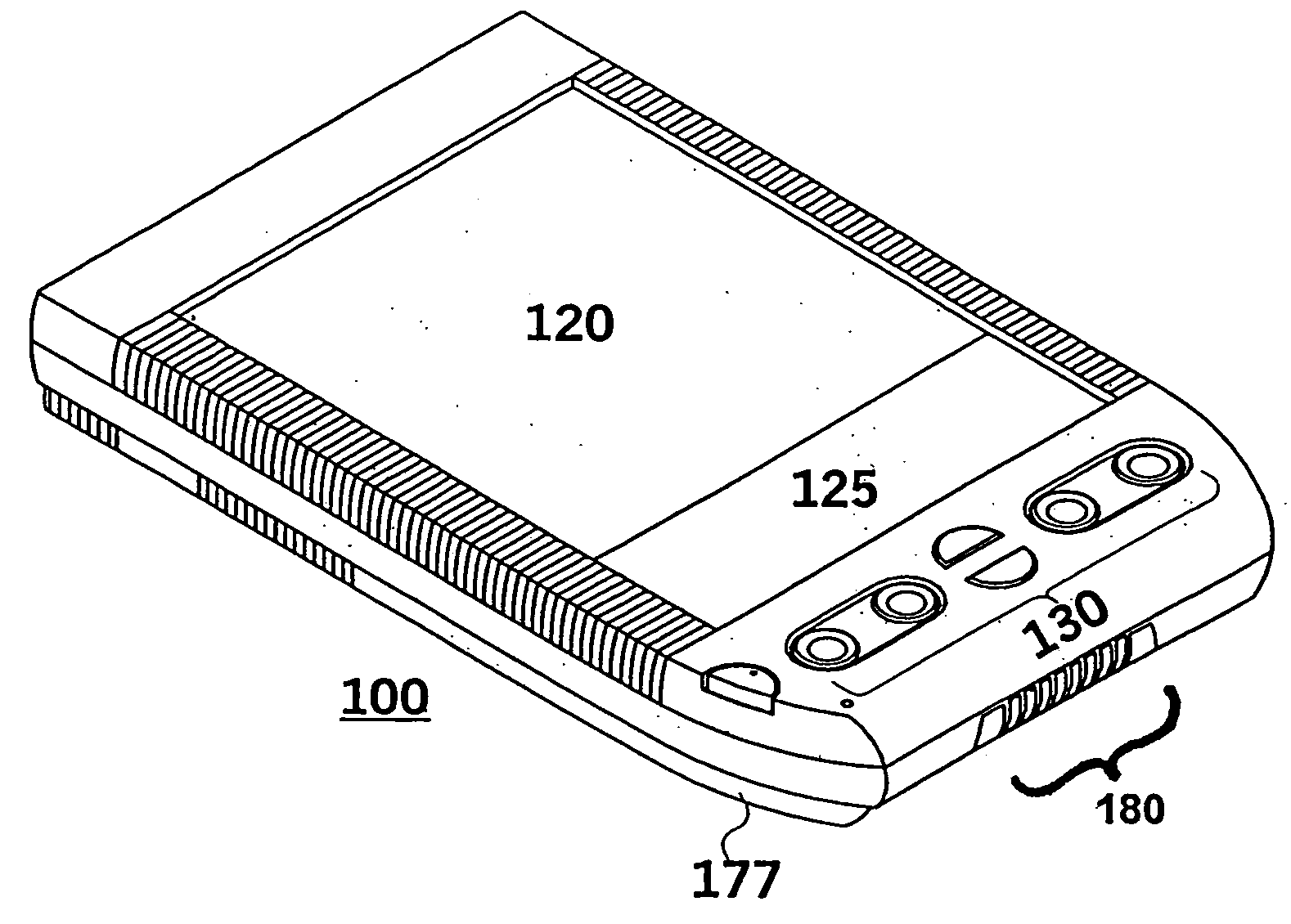
[0068]FIG. 4 illustrates one embodiment of a block diagram of hardware (e.g., solid state) elements of a wireless communications (e.g., telephony portion) of a handheld computer system. In one embodiment, the telephony portion can be a separate physical unit that couples through an expansion slot 410 is the connection portion 110 of the handheld computer system 100. In another embodiment, the telephony portion is integrated with the remainder of the handheld computer system, for example as previously illustrated and described with respect to FIGS. 3A and 3B. By way of example, the telephony portion will be described in the context of the separate physical unit with respect to FIG. 4, although the principles of operation are applicable for the integrated telephony and handheld computer system embodiment. The example in FIG. 4 of the handheld computer system 100 may also be referenced as a personal digital assistant or organizer.

[0069] In FIG. 4, the expansion slot 410 is coupled to t...

second embodiment

[0169]FIG. 23 illustrates an incoming call alert screen view that informs the user of an incoming call. The embodiment of an incoming call screen is illustrated in FIG. 23 is delivered when the flip lid 320 of the integrated computer and cellular telephone system illustrated in FIG. 3A is closed. The user may answer the incoming telephone call opening the lid 320 of the integrated computer and cellular telephone system. Similarly, the user may ignore the telephone call (and thus stop the ringing) by tapping the upward scroll button.

[0170] If an incoming telephone call is received while the user is opening or closing the flip lid 320 or presses a button on the integrated computer and cellular telephone system, an undesirable action may occur. For example, if the user is opening the flip lid 320 while an incoming call is being received, then the user may inadvertently answer the telephone call without having a chance to review the caller-ID field. Similarly, a user may pressing the sc...


PUM


Abstract

A control mechanism for a mobile communication device includes a first mode element, a second mode element and a third mode element. Each mode element corresponds to a distinct operational mode associated with a particular function of the mobile communication device. A physical switch mechanism, which has a first physical positional state corresponding to the first mode element, a second physical positional state corresponding to the second mode element, and a third physical positional state corresponding to the third mode element, is movable between each physical positional state to select an operational mode and to enable the mode element corresponding to the selected operational mode.

Description

CROSS REFERENCE TO RELATED APPLICATIONS [0001] This patent application is a continuation-in-part of, and claims priority to, U.S. patent application Ser. No. 09 / 977,871, filed Oct. 14, 2001, titled “Method and Apparatus for Accessing a Contacts Database and Telephone Services”, which is a continuation-in-part of the U.S. patent application Ser. No. 09 / 668,123, filed Sep. 21, 2000 and entitled “Method and Apparatus for Organizing Addressing Elements”, now U.S. Pat. No. 6,781,575, and a continuation-in-part of the U.S. patent application Ser. No. 09 / 374,095, filed Aug. 12, 1999, titled “Mobile Computer System Designed for Wireless Communication Expansion”, now U.S. Pat. No. 6,516,202, the contents of each herein-being incorporated by reference.BACKGROUND [0002] 1. Field of the Art [0003] The present invention relates to the field of mobile computer systems, and more particularly, to handheld computer system that includes a configuration for a wireless data and voice communications. [0...

Claims


Application Information

Patent Timeline
IPC IPC(8): H04M1/00
CPCH04M1/0214H04M1/0235H04M1/0254H04M1/274508H04M1/27455H04M1/274558H04M1/274583H04M1/56H04M1/57H04M1/72522H04M1/7255H04M1/72583H04M19/04H04M2250/22H04M2250/60H04M1/27453H04M1/2746H04M1/27475H04M1/2748H04M1/72403H04M1/72433H04M1/72469
Inventor HAWKINS, JEFFREY CHARLESHAITANI, ROBERT YUJI
Owner HEWLETT PACKARD DEV CO LP
Learn More