State determination device for internal combustion engine

a technology of internal combustion engine and determination device, which is applied in the direction of electric control, fuel injection apparatus, charge feed system, etc., can solve the problem that the air-fuel ratio may deviate from the desired air-fuel ratio

Inactive Publication Date: 2006-09-21
TOYOTA JIDOSHA KK
View PDF8 Cites 28 Cited by
  • Summary
  • Abstract
  • Description
  • Claims
  • Application Information

AI Technical Summary

Benefits of technology

[0017] According to the present invention, the third determination unit determines the fuel injection mechanism as abnormal when deviation between the actual time period for fuel injection from the fuel injection mechanism and the predetermined time period is greater than the predetermined

Problems solved by technology

Accordingly, when an erroneous intake air amount is detected due to abnormality in the airflow meter (an

Method used


Image

  • State determination device for internal combustion engine
  • State determination device for internal combustion engine
  • State determination device for internal combustion engine

Examples


first embodiment

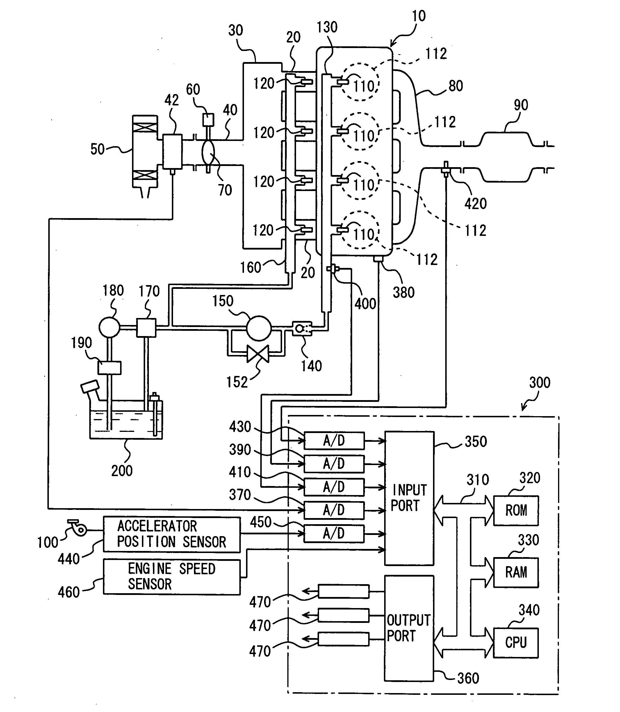
[0033]FIG. 1 schematically shows a configuration of an engine system controlled by an engine ECU (Electronic Control Unit) that is a state determination device of an internal combustion engine according to a first embodiment of the present invention. Although an in-line 4-cylinder gasoline engine is shown in FIG. 1, application of the present invention is not restricted to the engine shown, and the present invention is applicable to various types of engines such as a V-type 6-cylinder engine, a V-type 8-cylinder engine and the like.

[0034] As shown in FIG. 1, an engine 10 includes four cylinders 112, which are connected via corresponding intake manifolds 20 to a common surge tank 30. Surge tank 30 is connected via an intake duct 40 to an air cleaner 50. In intake duct 40, an airflow meter 42 and a throttle valve 70, which is driven by an electric motor 60, are disposed. Throttle valve 70 has its opening position controlled based on an output signal of an engine ECU 300, independentl...

second embodiment

[0103] Referring to FIGS. 10 and 11, a second embodiment of the present invention will be described. In the present embodiment, DI ratio r is calculated using a map different from those in the first embodiment described previously.

[0104] As the configuration and the process flow as well as functions thereof are otherwise the same as those in the first embodiment described previously, detailed description thereof will not be repeated.

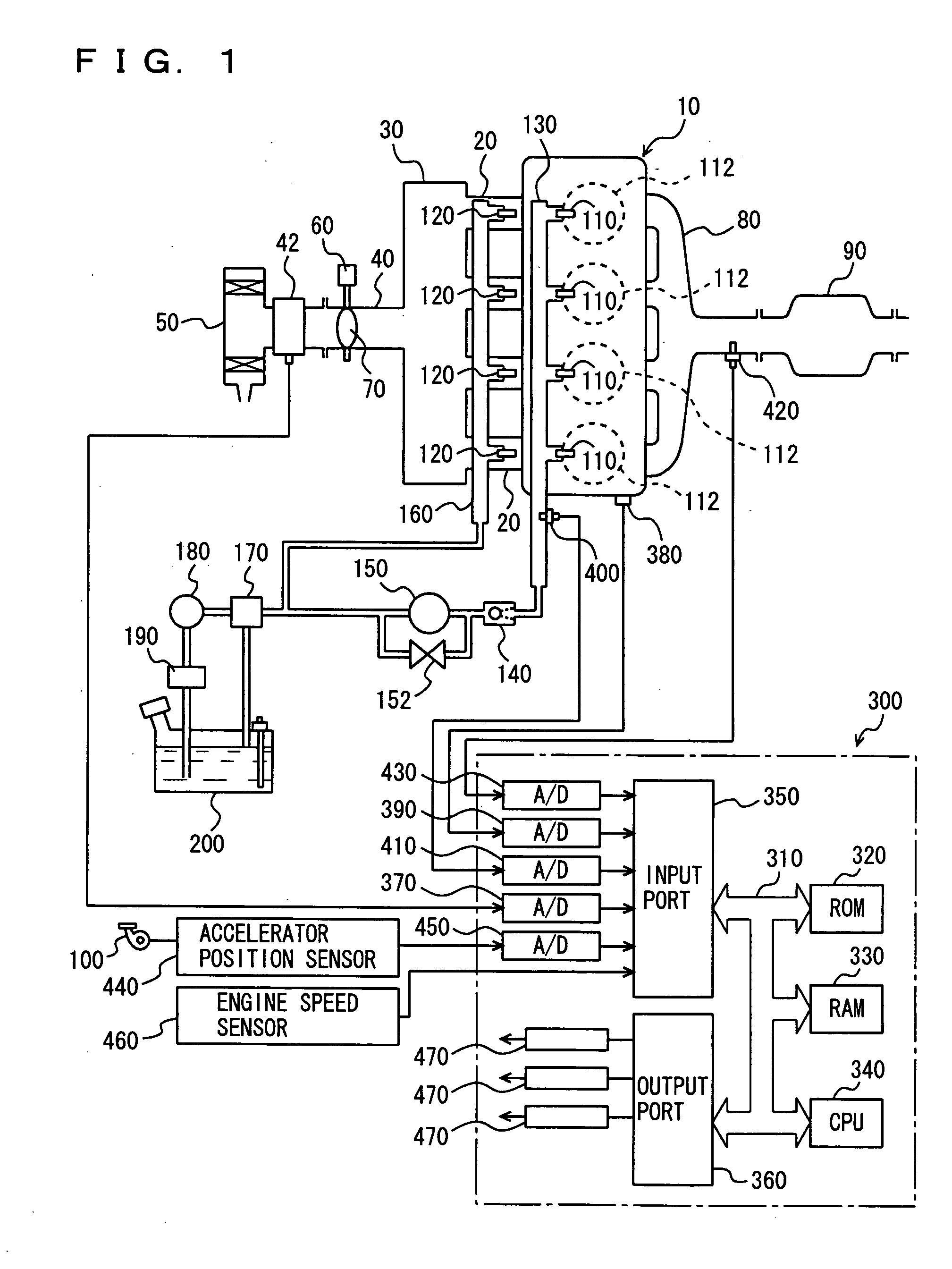
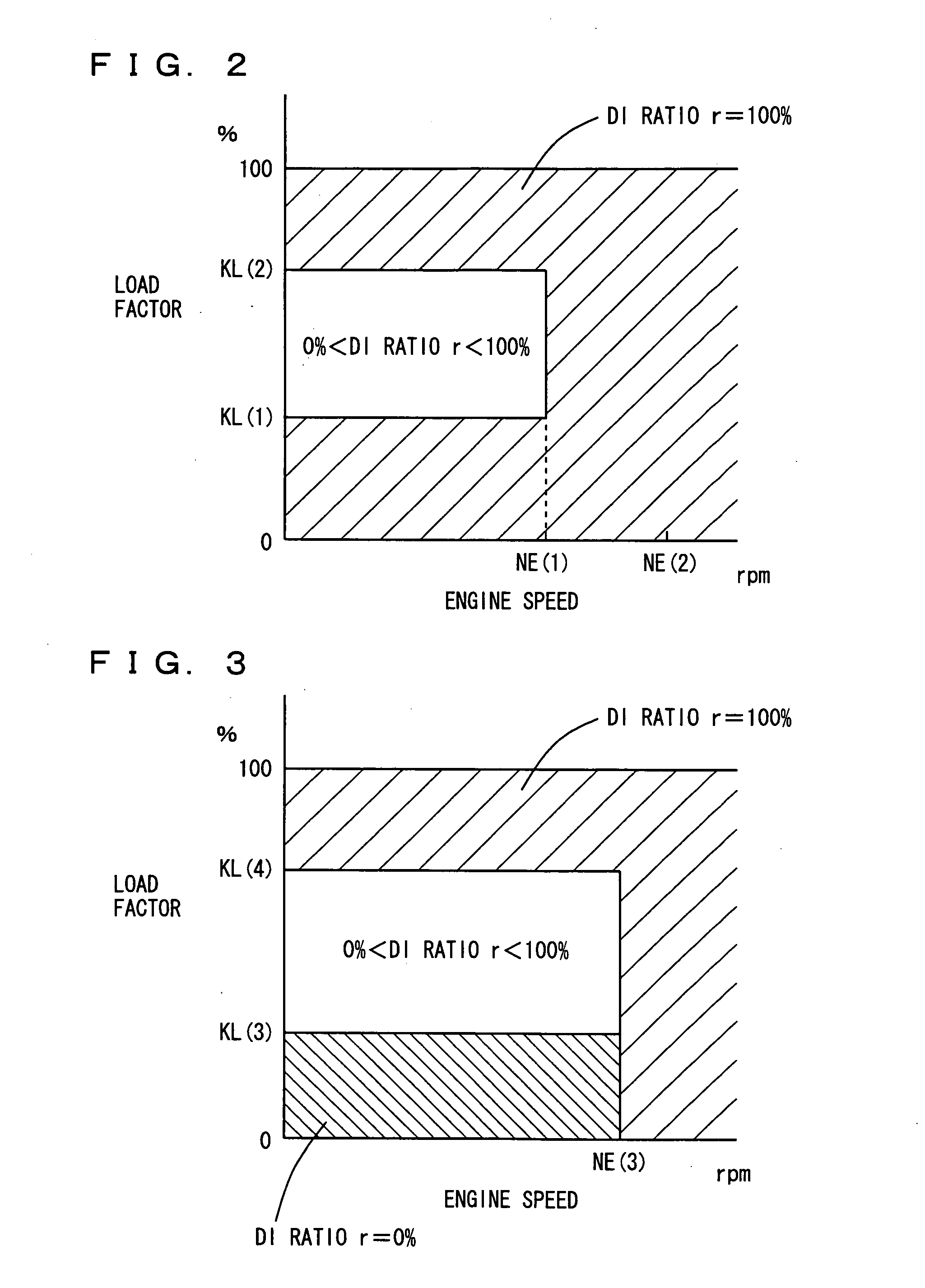
[0105] Referring to FIGS. 10 and 11, maps each indicating the fuel injection ratio between in-cylinder injector 110 and intake manifold injector 120, identified as information associated with the operation state of engine 10, will be described. The maps are stored in ROM 320 of engine ECU 300. FIG. 10 is the map for the warm state of engine 10, and FIG. 11 is the map for the cold state of engine 10.

[0106]FIGS. 10 and 11 differ from FIGS. 2 and 3 in the following points. “DI RATIO r=100%” holds in the region where the engine speed of engine 10 is equal...


PUM


Abstract

An engine ECU executes a program including the steps of: determining an airflow meter as abnormal when the number of times an injector is determined as abnormal (abnormality determination count C) is greater than a threshold value C(0) in all of a region where DI ratio r=100%, a region where DI ratio r=0%, and a region where 0%<DI ratio r<100%, and determining the airflow meter as normal when abnormality determination count C is smaller than the threshold value C(0) at least in any one region.

Description

[0001] This nonprovisional application is based on Japanese Patent Application No. 2005-078311 filed with the Japan Patent Office on Mar. 18, 2005, the entire contents of which are hereby incorporated by reference. BACKGROUND OF THE INVENTION [0002] 1. Field of the Invention [0003] The present invention relates to a state determination device for an internal combustion engine that includes a fuel injection mechanism (in-cylinder injector) injecting fuel into a cylinder and a fuel injection mechanism (intake manifold injector) injecting fuel into an intake manifold or an intake port, and more particularly to a technique to determine a state of a detection unit (airflow meter) that detects an intake air amount based on a state of the fuel injection mechanism. [0004] 2. Description of the Background Art [0005] An internal combustion engine provided with an intake manifold injector for injecting fuel into an intake manifold and an in-cylinder injector for injecting fuel into a combustio...

Claims


Application Information

Patent Timeline
IPC IPC(8): F02B7/00
CPCF02D41/1454F02D41/18F02D41/221F02D41/2445F02D41/2451F02D41/2454F02D41/3094F02M63/029F02M69/046F02D41/222
Inventor TAHARA, TATSUYA
Owner TOYOTA JIDOSHA KK
Why Eureka
Try Eureka