Screw-on closure for a recipient

a screw-on cap and recipient technology, applied in the direction of closure lids, closure stoppers, caps, etc., can solve the problems of deformation of the outer appearance of the screw-on cap, unreliable operation of current tamper-resistant systems, and insufficient assurance, so as to simplify the screw-on cap manufacturing and filling line application process, the effect of eliminating the tamper-resistant band

Inactive Publication Date: 2006-09-21
BARANGUA
View PDF18 Cites 15 Cited by
  • Summary
  • Abstract
  • Description
  • Claims
  • Application Information

AI Technical Summary

Benefits of technology

[0017] Another object of the invention is to eliminate the tamper-resistant band of other systems so as to simplify the container recovery line in the recycling industry, since if there is no tamper-resistant band on the neck of the container to be recycled, it is possible to eliminate the tool responsible for removing said band from the neck of the recipient. It must be noted that the container and the tamper-resistant band are made of different materials, therefore they must be separated in order to be recovered.
[0018] Yet another object of the invention is to simplify screw-on cap manufacture and filling line application processes.
[0019] It must be noted that merely eliminating the resistance of the stop profiles incorporated on current tamper-resistant bands allows simplifying and economizing the manufacture of the tools or molds on one hand, and improving industrial efficacy on the other. All this is done without jeopardizing the industrial processes and tools for the containers which, if desired, can be lighter in weight without losing strength as a result.
[0020] Upon eliminating the current stop profiles from the neck of the container, the screwing resistance is reduced to a maximum, allowing high accuracy and a low screw torque, which results in the effectiveness of the application or capping machines, increasing their performance and operating life.
[0021] Another objective of the invention is to improve the efficacy, operating life and quality of screw-on cap manufacturing processes. As a result, the manufacturing and filling system is also low-cost.

Problems solved by technology

However, this type of sealing systems has some drawbacks resulting, for example, from the existence of a circular ring under the screw thread / screw threads on the neck of the recipient.
As a result, to perform said screwing on in the filling line, it is necessary to carry out a high screw torque to assure an effective screwing on, which on many occasions cannot be specified, and on other occasions deforms the outer appearance of the screw-on cap due to an excess.
Another problem is that the functioning of current tamper-resistant systems is not absolutely reliable either, that is, they do not 100% assure the leak-tightness of the container due to the breaking or detaching of the tamper-resistant band incorporated to the cap, since any partial turn prior to the complete unscrewing of the cap or closure causes a loss of the leak-tightness, and therefore the real possibility of a leak or introduction of liquid into the container without the band having been broken or detached.
Upon beginning to unscrew the cap, there is an audible noise caused by the carbonated gas leaving the inside of the container.
Therefore, the initial contents of the container may be altered, and as a result the end consumer may loose trust in the contents, which would result in a loss of sales for the manufacturer.

Method used


Image

  • Screw-on closure for a recipient
  • Screw-on closure for a recipient
  • Screw-on closure for a recipient

Examples


Embodiment Construction

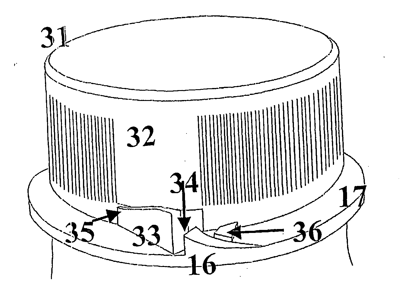
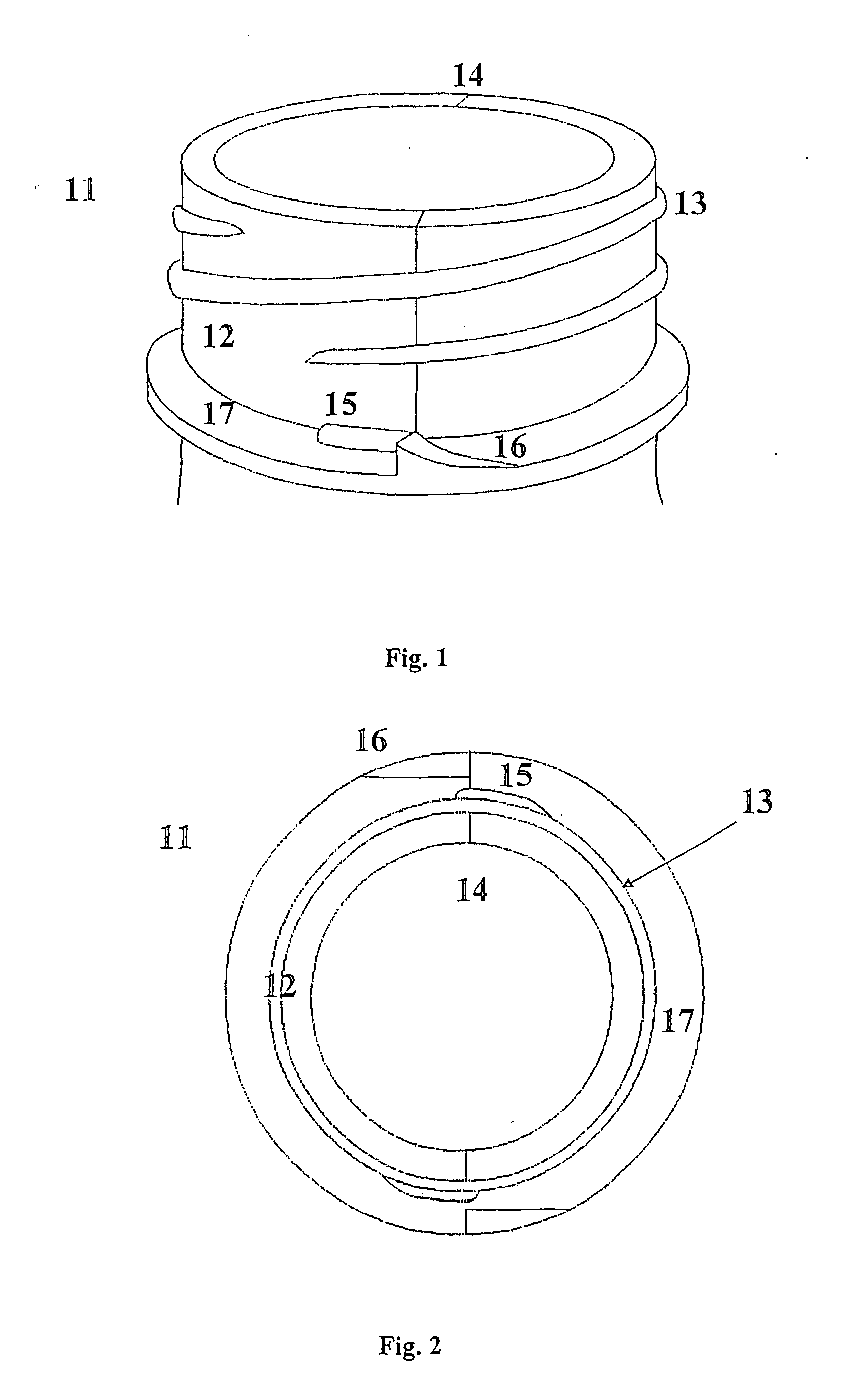
[0029]FIG. 1 represents a retention or locking device 15, 16 located under the outer screw thread or threads 13 located on the neck 12 of a container or recipient 11. The recipient 11 is preferably made of a plastic material so that the material can be injected in an injection mold. The recipient 11 is suitable for storing a substance such as a liquid, a carbonated beverage or the like.

[0030] The retention device comprises a first projection 15 and a second projection 16 or ribs close to the contact edge 14 of each one of the two parts or halves constituting the container 11.

[0031] As can be seen in FIG. 2, each half of the container includes a first rib 15 and a second rib 16, each one of them located at one of the contact edges corresponding to one half of the container 11. For example the first rib 15 is in contact with the neck 12, that is, in contact with the outer face of the cylinder of the neck of the container 11 and on a horizontal base ring 17 which is located under the...


PUM


Abstract

A screw-on cap (31) for a recipient including a retention flap (33) and a locking device comprising a first rib and a second rib (16), such that in the first screwing on of the screw-on closure (31) the retention flap (33) is deviated so as to be able to pass between the first rib and the second rib (16) and in the final position, the retention flap (33) butts against a contact surface of the second rib (16) in a secure and reliable manner.

Description

OBJECT OF THE INVENTION [0001] The present invention refers to a screw-on closure or cap for closing a recipient. [0002] More specifically, the present invention refers to a screw-on cap comprising at least one detachable retention flap which can be screwed on or screwed off an outer screw thread belonging to a container for the purpose of preventing undue tampering of the contents stored inside the recipient. STATE OF THE ART [0003] Different sealing systems suitable for closing a recipient are currently known. Said sealing systems have the function of assuring the tamper-resistance of the contents stored in the recipient or container. [0004] A sealing system usually includes a tamper-resistant band joined to a screw-on cap or closure. Said bands, just like the caps to which they are incorporated, are cylindrical and are vertically joined to the also cylindrical body of the cap or closure in the lower portion thereof and are provided with different internal stop profiles assuring, ...

Claims


Application Information

Patent Timeline
Patent Type & Authority Applications(United States)
IPC IPC(8): B65D41/04B65D51/00B65B7/28B65D41/34B65D50/04B65D55/02
CPCB65D41/3409B65D50/046B65D55/022
Inventor BASTERO LOPEZ, JESUS MARIA
Owner BARANGUA
Why Eureka
Try Eureka