Gas producer

Inactive Publication Date: 2006-09-21
NIPPON KAYAKU CO LTD
View PDF36 Cites 14 Cited by
  • Summary
  • Abstract
  • Description
  • Claims
  • Application Information

AI Technical Summary

Benefits of technology

[0022] This construction can provide the structure that can prevent the secondary charge holder from being burst until an inner pressure of the secondary charge holder reaches a predetermined pressure. This

Problems solved by technology

When the gas generant is burnt under such a condition, there is a possibility that the electrode pins in the body may be burst forth.
In addition, since

Method used


Image

  • Gas producer
  • Gas producer
  • Gas producer

Examples


first embodiment

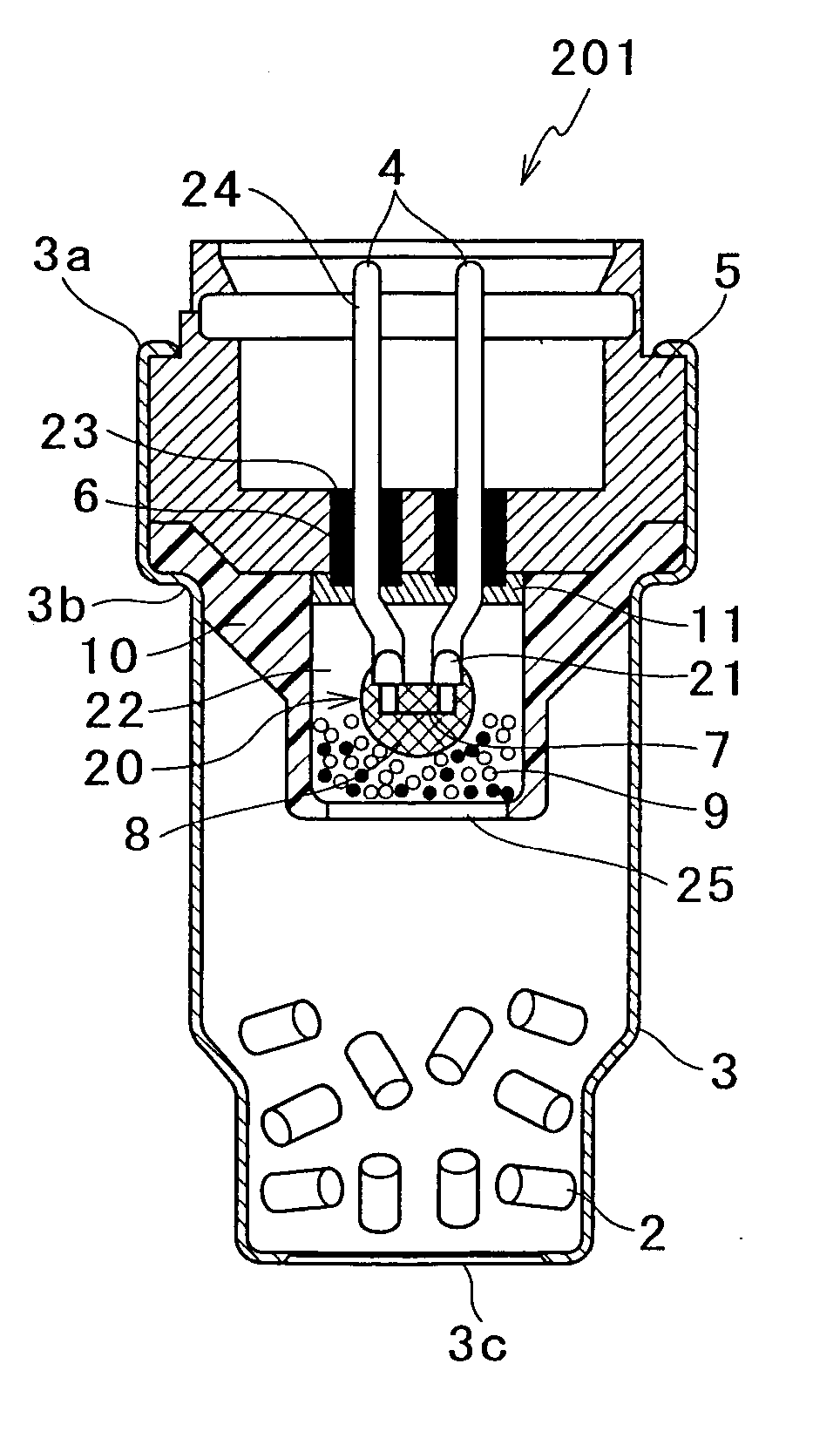
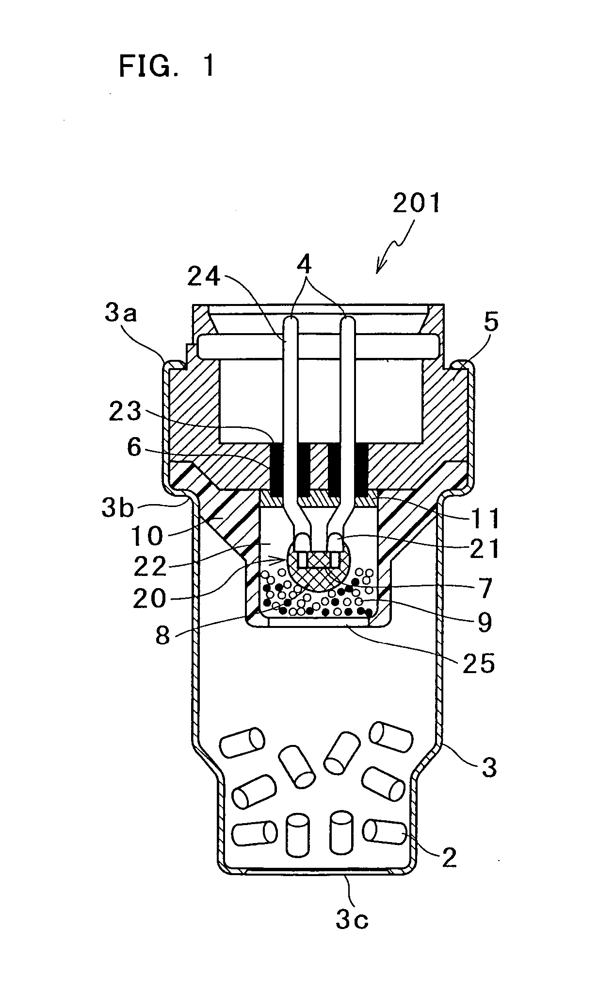
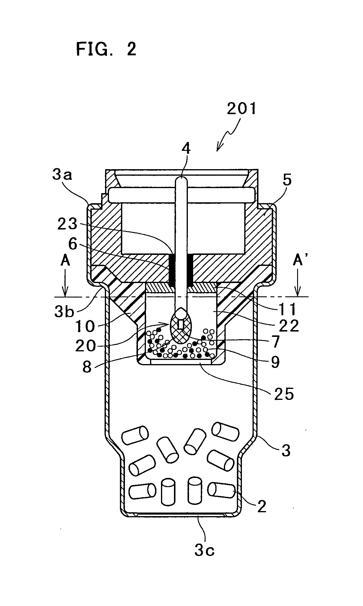
[0038] A first embodiment of a gas generator of the present invention will be described with reference to FIGS. 1 to 4.

[0039] In FIG. 1, a gas generator 201 of this embodiment comprises a cup member 3 packed with gas generant 2 to generate gas by the burning, and an ignition portion 20 which includes a pair of electrode pins 4 arranged in parallel and having a heating element 7 at the other ends thereof 21 on the side projecting toward the cup member 3, and a primary charge 8 formed to cover the heating element 7 and which is fixed to the holder 5. A pad 11 is arranged at root portions of the electrode pins 4 on the other side 21, for preventing the secondary charge 9 being accidentally ignited by a spark caused by static electrical charge and the like.

[0040] A secondary charge holder 10 is sandwiched between the holder 5 and a diameter-reduction portion 3b of the cup member 3. In the secondary charge holder 10, the ignition portion 20 and a combustion chamber 22 containing the se...

second embodiment

[0053] A second embodiment of the gas generator of the present invention will be described with reference to FIGS. 5 to 7. In this embodiment, common parts to those of the gas generator 201 of the first embodiment as described above are labeled by the same reference numerals and characters and the detailed description thereon is omitted.

[0054] One of the differences of a gas generator 202 of this embodiment shown in FIGS. 5-7 from the gas generator 201 of the first embodiment shown in FIGS. 1-4 is in that the ignition portion 20 comprises electric conductors 12 for allowing passage of electricity, a joining portion 13 for joining together the electric conductors 12, a heating element 7 for converting electric signals to heat, and a primary charge 8 formed around the heating element 7. The electric conductors 12 and the electrode pins 4 are fixed together by welding, crimping, soldering, brazing, or other proper means. Another difference of the gas generator 202 from the gas generat...

third embodiment

[0059] Next, a third embodiment of the gas generator of the present invention will be described with reference to FIGS. 8 to 10. In this embodiment, common parts to those of the gas generators 201, 202 of the first and second embodiments as described above are labeled by the same reference numerals and characters and the detailed description thereon is omitted.

[0060] One of the differences of a gas generator 203 of this embodiment shown in FIGS. 8-10 from the gas generator 202 of the second embodiment shown in FIGS. 5-7 is in that the combustion chamber 22 formed in the secondary charge holder 10 is arranged eccentrically with respect to a central axis of the gas generant 2. In this embodiment, the electric conductors 12 of the ignition portion 20 are fixed to the electrode pins 4 in the state of being bent into a 90° angle (See FIG. 9). This can make the good use of a radial space of the interior of the gas generator 203 to arrange the combustion chamber 22, thus providing an incr...


PUM


Abstract

A gas generator comprising a cup member 3 loading therein with gas generant 2 to generate gas by burning, at least two electrode pins 4 to permit passage of electricity, an ignition portion 20 having an ignition mechanism to ignite by an application of electric current, and a holder 5 to fix the electrode pins 4 and the ignition portion 20 in place and engage with the cup member 3 to seal off the gas generant 2, wherein holes 23 for the electrode pins 4 to be extended through are formed in the holder 5 and plastic members 6 are arranged around a part of a radial periphery of the respective electrode pins 4, and wherein a part of or a whole of the plastic members 6 are inserted in the holes 23 and the holder 5 is plastically deformed at a portion thereof at which the plastic members 6 are inserted, whereby the electrode pins 4 and the plastic members 6 are fixed.

Description

TECHNICAL FIELD [0001] The present invention relates to a gas generator, particularly related to a gas generator suitably used for operating a vehicle occupant restraint system, as an automobile seatbelt pretensioner and the like. BACKGROUND ART [0002] The seatbelt pretensioner is known as one of the safety systems to protect a vehicle occupant from the shock in a car collision. The seatbelt pretensioner operate on a large amount of high-temperature and high-pressure gas produced from the gas generator, for the protection of the vehicle occupant. The gas generator includes an igniter device and gas generant and is structured so that when a car collision happens, the igniter ignites and burns the gas generant, so as to generate the large amount of gas rapidly. [0003]FIG. 15 shows an example of a conventional gas generator of JP Unexamined Laid-open Patent Publication No. 2000-260815. The gas generator 101 of FIG. 15 comprises a cup member 103 packed with gas generant 102, an igniter ...

Claims


Application Information

Patent Timeline
IPC IPC(8): F42B3/12F15B21/12B60R22/36
CPCB60R21/26B60R2021/26029F15B15/19
Inventor KUBO, DAIRIKURITA, KAZUMASA
Owner NIPPON KAYAKU CO LTD
Why Eureka
Try Eureka