Projection unit for a head-up display

a projection unit and display technology, applied in the direction of instruments, optics, cathode-ray tube indicators, etc., can solve the problems of high cost and difficulty in manufacturing free-form mirrors, and achieve the effect of reducing installation space and cost, good distortion correction, and positive effect on overall imaging quality

Active Publication Date: 2006-09-21
SYPRO OPTICS
View PDF7 Cites 23 Cited by
  • Summary
  • Abstract
  • Description
  • Claims
  • Application Information

AI Technical Summary

Benefits of technology

[0022] The invention presents a construction which substantially mitigates the disadvantages of the prior art described above through comparatively simple means.
[0023] The core idea of the invention consists in that the function of the free-form surface is transferred from the mirror to the transmitting cover glass and all additional reflective components are constructed only as standard, simple spherical mirrors. A cover glass for sealing the optical opening in the dashboard scoop is also already contained in all previously known systems and, in the latter, is mostly designed with respect to surface shape and installation position in such a way that, as far as possible, no reflected light can reach the human eye. For example, an advantageous typical embodiment form is a concentric cylindrical meniscus with a 15-degree tilt relative to the principal ray with meniscus radii of approximately 300 mm. In order to make further use of the advantageous reflection suppression, the installation position and radii of curvature are left approximately the same as before and a free-form function bringing about the required imaging quality together with the additional spherical components is added at least to the underside of the cover glass. This arrangement has a number of substantial advantages:
[0025] 2. lower susceptibility to tolerances because the free-form surface is used in transmission and, further, fewer components are necessary in all;
[0027] 4. very large image sizes and eye box sizes are made possible at the same time with very good distortion correction over the entire eye box region.
[0028] In particular, it is possible by means of the invention to make do, apart from the cover glass, with only one optical imaging element in the form of a spherical mirror, which results in an enormous reduction in installation space and cost. The smaller deflecting angles that are therefore required at the spherical mirror have a very positive effect on the overall imaging quality which is appreciably better than in the previous known conventional multi-mirror systems.

Problems solved by technology

It has been shown in practice that the use of a plurality of mirrors requires considerable installation space, so that the requirements can only be met with great difficulty particularly for applications in passenger vehicles.
When using a maximum of four mirrors, this can only be achieved in that some mirrors must be constructed as free-form mirrors.
However, manufacture of free-form mirrors is very cost-intensive and, since reflections are involved, they are also particularly susceptible to tolerances relating to surface shape and accuracy of installation.

Method used


Image

  • Projection unit for a head-up display
  • Projection unit for a head-up display
  • Projection unit for a head-up display

Examples


Embodiment Construction

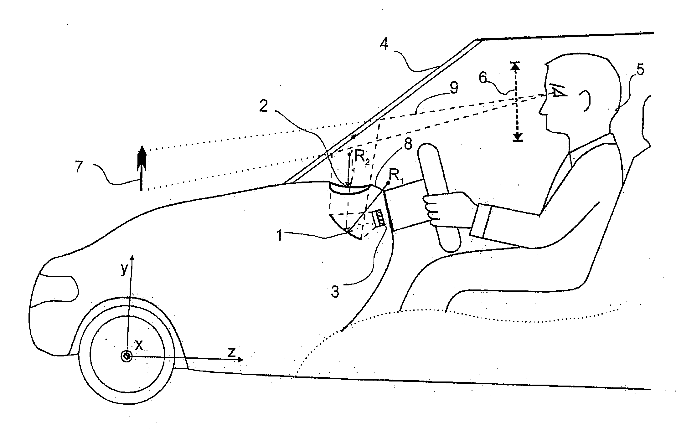
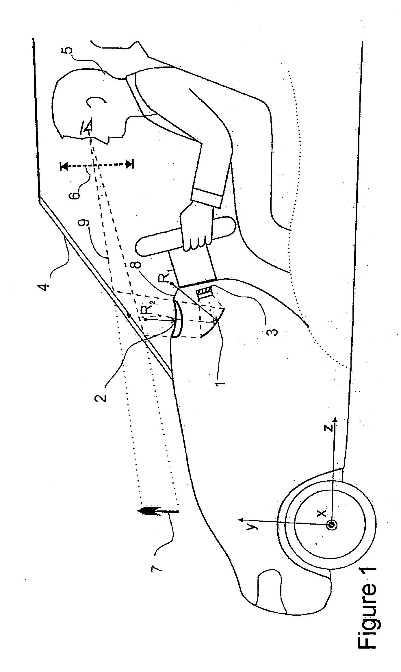
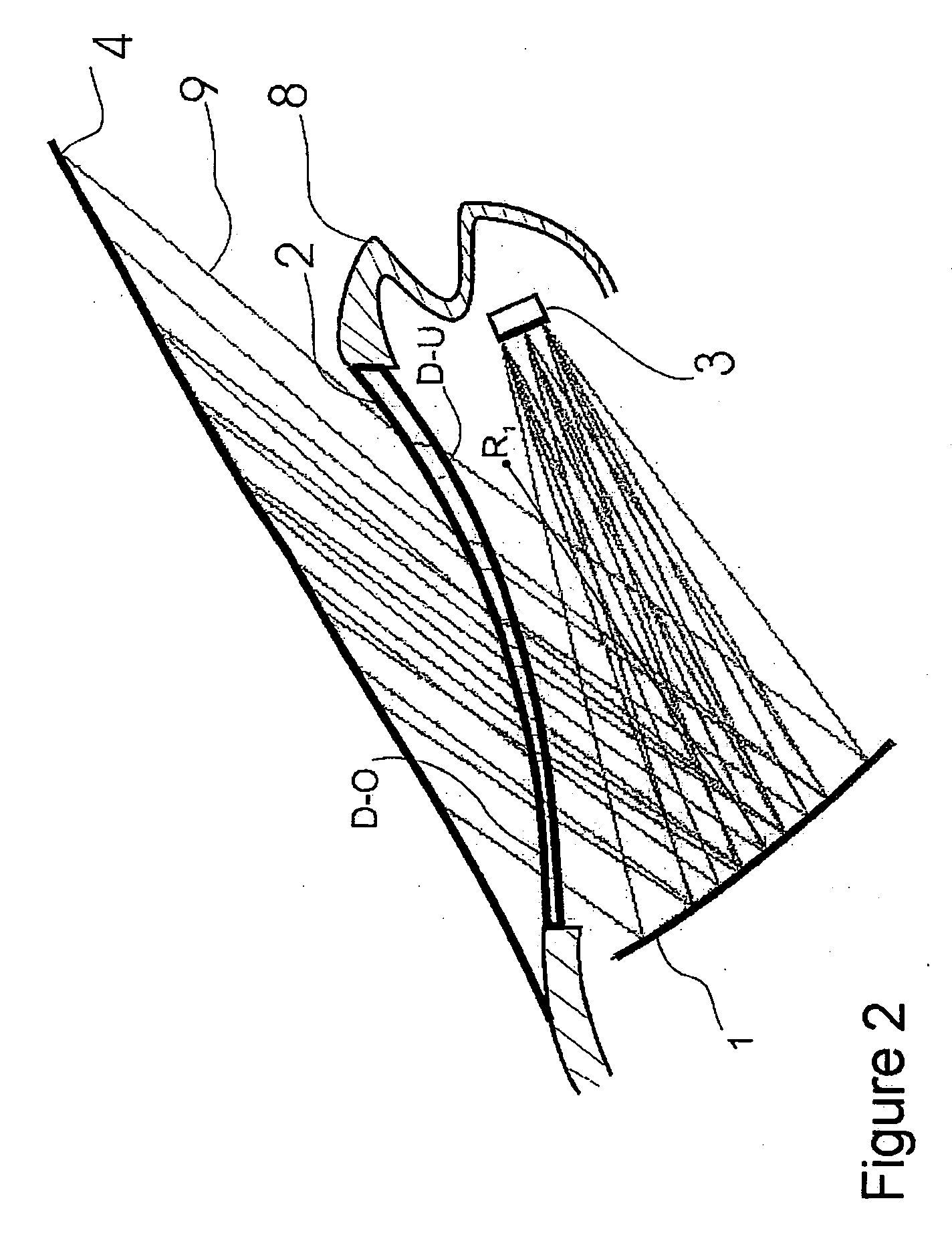
[0034]FIG. 1 is a schematic illustration of the construction of an optical system for a head-up display. An image generator 3 is arranged at a distance in front of a spherical mirror 1 which has a concave curvature with radius R1. This mirror 1 folds the beam path and exerts an imaging action. The mirror 1 guides the beam path 9 in direction of the windshield 4 through a cylindrical lens 2. The cylindrical lens 2 functions at the same time as a cover which closes the opening in the dashboard scoop 8.

[0035] The image generator 3 can comprise, for example, a lamp, a laser, or LEDs as light source and can be a DLP, LCOS or LCD type, for example. However, the image generator can also generate light itself and can be, e.g., a plasma panel.

[0036] In the following, the coordinates of the components refer to a global coordinate system. The origin of this coordinate system is located in the front vehicle axle. The positive Z-axis faces away from the driving direction, the positive X-axis f...


PUM


Abstract

The invention is directed to a projection unit for a head-up display comprising an image generator, a mirror and a refractive lens which are arranged in a housing one behind the other in the light propagation direction. The beam path is directed to a windshield. The invention is characterized in that the mirror has a concave reflection surface, and the lens has a free-form surface at least on one of the optically active surfaces (D-U and / or D-O).

Description

CROSS-REFERENCE TO RELATED APPLICATIONS [0001] This application claims priority of German Application No. 10 2005 012 011.3, filed Mar. 16, 2005, the complete disclosure of which is hereby incorporated by reference. BACKGROUND OF THE INVENTION [0002] a) Field of the Invention [0003] The invention is directed to a projection unit for a head-up display comprising an image generator, a mirror and a refractive lens which are arranged in a housing one behind the other in the light propagation direction, wherein the beam path is directed to a windshield. An arrangement of this kind is applied chiefly in automotive construction, but is not limited to this. [0004] b) Description of the Related Art [0005] EP 0 377 773 B1 shows a display device for a head-up display which contains an image generator, a mirror element and a transparent cover. The imaging characteristics are not mentioned. However, it can be gathered from the drawings that the mirror element is plane and the cover is plane-para...

Claims


Application Information

Patent Timeline
Patent Type & Authority Applications(United States)
IPC IPC(8): G02B27/14
CPCG02B27/0101G02B2027/011G02B2027/0118
Inventor DOBSCHAL, HANS-JUERGENJAHN, DIRK
Owner SYPRO OPTICS
Why Eureka
Try Eureka