Radio communication apparatus and subcarrier assignment method

Active Publication Date: 2006-09-21
GK BRIDGE 1
View PDF18 Cites 131 Cited by
  • Summary
  • Abstract
  • Description
  • Claims
  • Application Information

AI Technical Summary

Benefits of technology

[0007] It is therefore the object of the present invention to provide wireless communication apparatus and a subcarrier allocation method capable of improving

Problems solved by technology

This means that the amount of control information sent from communication terminal apparatus to the base station apparatus is enormous and the transmission rate therefore falls.
This means that the amount of

Method used


Image

  • Radio communication apparatus and subcarrier assignment method
  • Radio communication apparatus and subcarrier assignment method
  • Radio communication apparatus and subcarrier assignment method

Examples


first embodiment

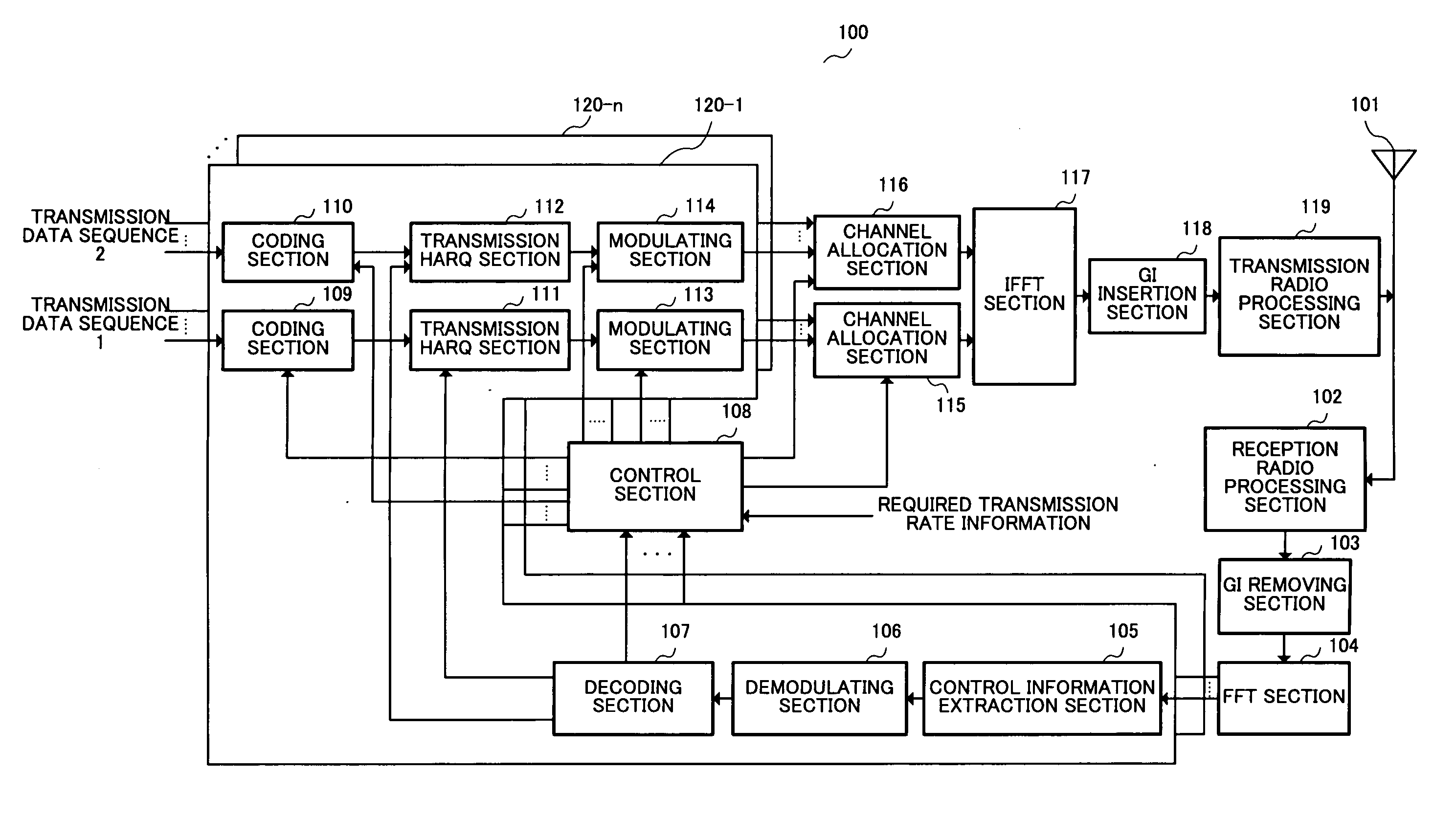
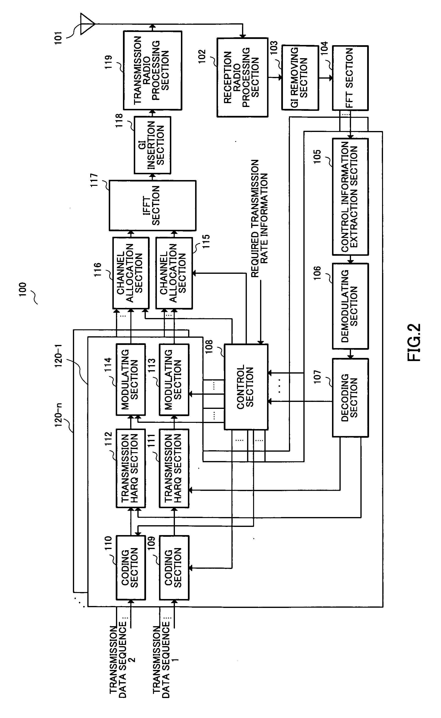
[0034]FIG. 2 is a block diagram showing a configuration for a wireless communication apparatus 100 of a first embodiment of the present invention.

[0035] Transmission data processing sections 120-1 to 120-n are each comprised of control information extraction section 105, demodulating section 106, decoding section 107, coding section 109, coding section 110, transmission HARQ (Hybrid Automatic Repeat Request) section 111, transmission HARQ section 112, modulating section 113 and modulating section 114. Transmission data processing sections 120-1 to 120-n are provided for the number of users and each of transmission data processing sections 120-1 to 120-n carries out processing on transmission data transmitted to one user.

[0036] A reception radio processing section 102 down converts a signal received at an antenna 101 from a radio frequency to a baseband frequency to output to a guard interval (hereinafter referred to as “GI”) removing section 103.

[0037] The GI removing section 103...

second embodiment

[0091]FIG. 8 is a block diagram showing a configuration for wireless communication apparatus 700 of a second embodiment of the present invention.

[0092] As shown in FIG. 8, wireless communication apparatus 700 of this second embodiment is wireless communication apparatus 100 of the first embodiment shown in FIG. 2 with data amount measuring section 701 and used channel determination section 702 added. In FIG. 8, portions with the same configuration as for FIG. 2 are given the same numerals and are not described.

[0093] Transmission data processing sections 703-1 to 703-n are each constituted by control information extraction section 105, demodulating section 106, decoding section 107, coding section 109, coding section 110, transmission HARQ (Hybrid Automatic Repeat Request) section 111, transmission HARQ section 112, modulating section 113, modulating section 114, data amount measuring section 701, and used channel determination section 702. Transmission data processing sections 70...

third embodiment

[0104]FIG. 10 is a block diagram showing a configuration for a wireless communication apparatus 900 of a third embodiment of the present invention.

[0105] As shown in FIG. 10, wireless communication apparatus 900 of this third embodiment is wireless communication apparatus 100 of the first embodiment shown in FIG. 2 with pilot signal extraction section 901, movement speed estimation section 902 and used channel determination section 903 added. In FIG. 10, portions with the same configuration as for FIG. 2 are given the same numerals and are not described.

[0106] Transmission data processing sections 904-1 to 904-n are each comprised of control information extraction section 105, demodulating section 106, decoding section 107, coding section 109, coding section 110, transmission HARQ (Hybrid Automatic Repeat Request) section 111, transmission HARQ section 112, modulating section 113, modulating section 114, pilot signal extraction section 901, movement speed estimation section 902, a...


PUM


Abstract

Wireless communication apparatus capable of increasing transmission efficiency by selecting data for scheduling according to data type, and capable of achieving low power consumption and high-speed signal processing is disclosed. With this apparatus, a control section (108) allocates transmission data sequence 1 to subcarriers of superior quality by carrying out scheduling for the transmission data sequence 1 based on CQI sent from communication terminal apparatus and required transmission rate information for each communication terminal apparatus, and allocates transmission data sequence 2 to preassigned subcarriers. Channel allocation section (115) allocates data for transmission data sequence 1 to subcarriers designated by control section (108). Channel allocation section (116) allocates data for transmission data sequence 2 to subcarriers designated by control section (108).

Description

TECHNICAL FIELD [0001] The present invention relates to a wireless communication apparatus and subcarrier allocation method, and particularly to a wireless communication apparatus and subcarrier allocation method where data is allocated to a plurality of subcarriers using, for example, OFDM. BACKGROUND ART [0002] In the related art, multi-carrier transmission such as OFDM and MC-CDMA etc. has been examined as a beyond 3G system taken as a system fulfilling high-speed packet transmission requirements. It is possible to improve frequency utilization efficiency in multi-carrier transmission by carrying out adaptive modulation and scheduling every subcarrier and by allocating data transmitted to each mobile station to subcarriers of superior reception quality within the communication band width using frequency scheduling. At base station apparatus, in order to carry out frequency scheduling by allocating data to be transmitted to each mobile station to subcarriers of superior reception ...

Claims


Application Information

Patent Timeline
IPC IPC(8): H04J11/00H04J3/22H04J3/16H04L5/02H04L27/26H04W72/04H04W72/12
CPCH04L5/0007H04L5/0016H04L5/0046H04L5/0057H04L25/0228Y02B60/50H04L5/006Y02D30/70H04W72/0453H04L1/0026H04W72/54H04L27/26H04L1/0003H04W88/08
Inventor NISHIO, AKIHIKO
Owner GK BRIDGE 1
Why Eureka
Try Eureka