Mobile communication system, communication control method and a mobile station

a mobile communication system and control method technology, applied in the direction of connection management, high-level techniques, sustainable buildings, etc., can solve the problems of insufficient battery life the power consumption of the mobile station with dual-mode capability is bigger, etc., and achieve the effect of power saving for the battery in the mobile station

Active Publication Date: 2006-09-21
NEC CORP
View PDF14 Cites 14 Cited by
  • Summary
  • Abstract
  • Description
  • Claims
  • Application Information

AI Technical Summary

Benefits of technology

[0010] The purpose of the present invention is to provide the mobile communication system which enables power consumption reduction for the mobile station with dual mode capability by unifying the location registration and paging processing for every mobile communication system.
[0014] According to the present invention, since it is enough for the mobile station with dual mode capability, which is used in a plurality of radio communication systems, to perform location registration processing and paging processing to only one of radio communication systems, power-savings for a battery in the mobile station can be realized.
[0015] According to the present invention, since location registration processing and paging processing which should usually be performed by each radio communication network are handled by a particular radio communication system, the radio communication network, which is not required for performing location registration processing and paging processing, can be constructed with a simple system, without incorporating location registration processing and paging processing.

Problems solved by technology

Therefore, the mobile station with dual mode capability requires bigger power consumption during the standby state compared with conventional mobile station (with a single mode capability), and it causes a problem that a battery of the mobile station with dual mode capability does not last longer than conventional mobile station.

Method used


Image

  • Mobile communication system, communication control method and a mobile station
  • Mobile communication system, communication control method and a mobile station
  • Mobile communication system, communication control method and a mobile station

Examples


Embodiment Construction

[0026] An exemplary embodiment of the present invention and various advantages of the present invention will be explained in detail below, with reference to drawings.

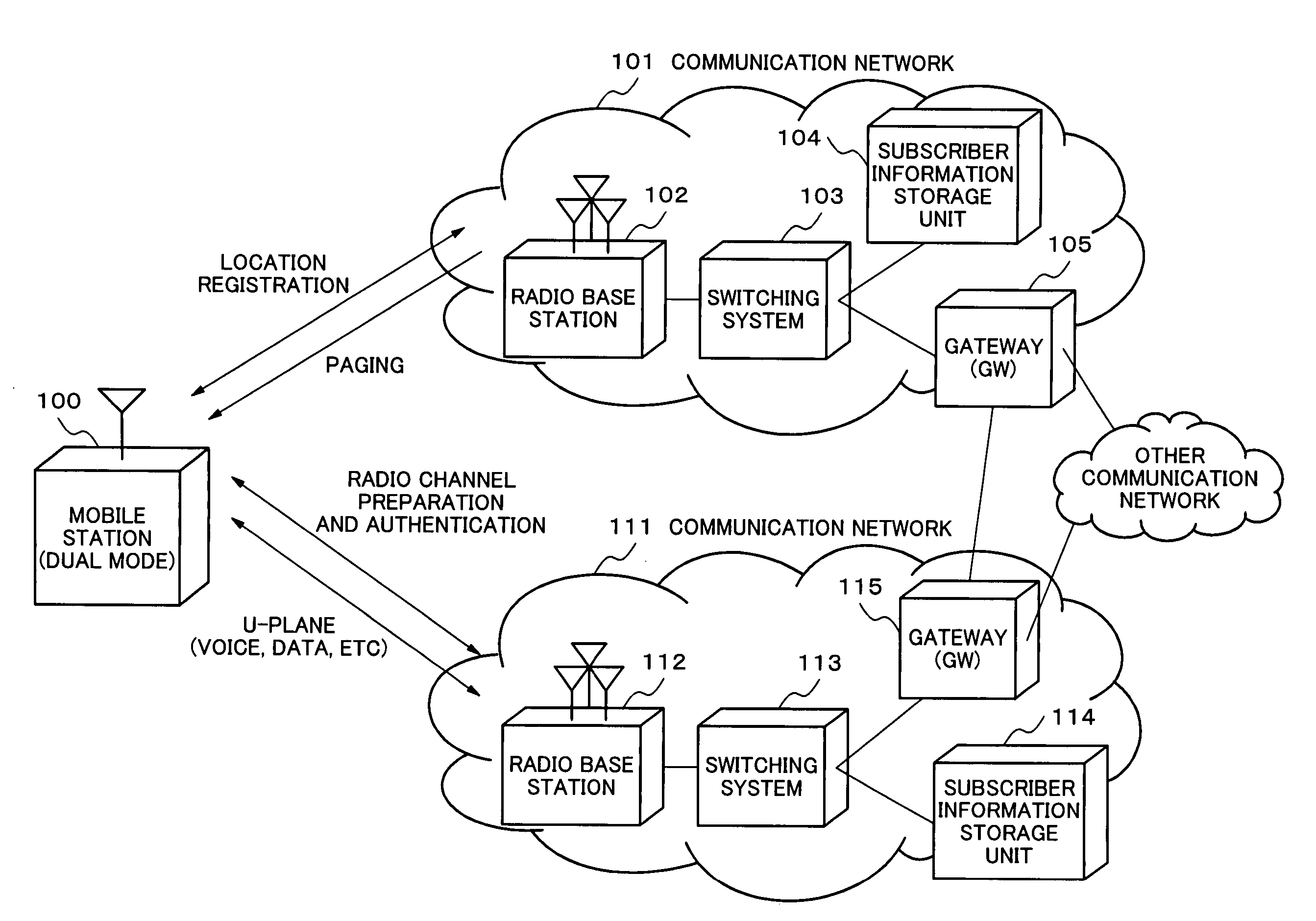
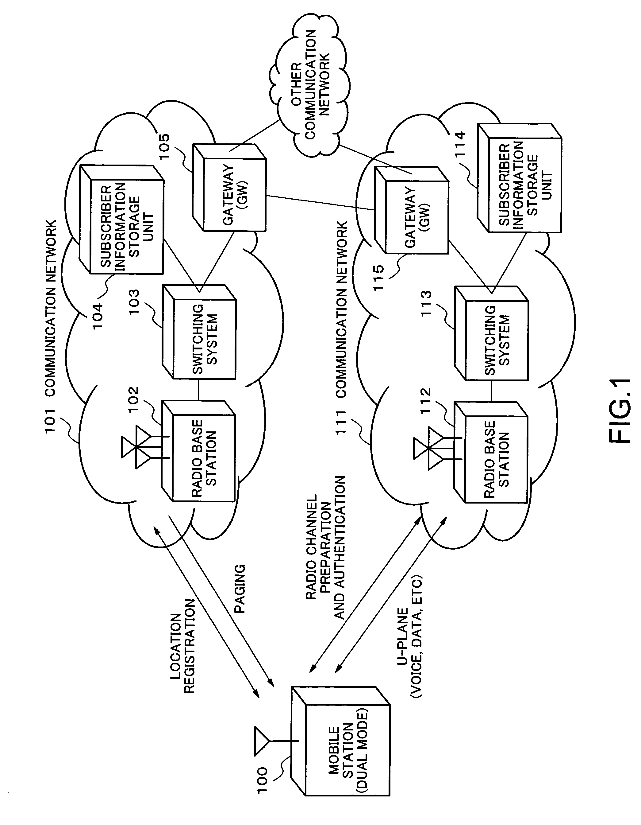
[0027]FIG. 1 is a system block diagram according to the exemplary embodiment of the present invention.

[0028] In FIG. 1, a mobile station 100 is dual mode terminal equipment, and communication networks 101, 111 are different kind of communication systems respectively. The communication network 100 can be one of systems of the present mobile communication systems, such as W-CDMA, cdma2OOO, cdmaone, GSM, AMPS, PDC, PHS, etc., which has functions to perform location registration and paging processing necessary for mobile communications control. The communication network 111 can be one of systems of present W-LAN, a cordless telephone, and present mobile communication systems, such as W-CDMA, cdma2OOO, cdmaone, GSM, PDC, PHS, etc., which has a radio channel control function. Here, each of the communication networks 101, 11...


PUM


Abstract

The present invention is to provide the mobile communication system which enables power consumption reduction for the mobile station with dual mode capability by unifying the location registration and paging processing for every mobile communication system. The mobile communication system is so arranged to perform location registration processing and paging processing for the mobile station by only one of radio communication systems. And the mobile station can access to any other radio communication systems.

Description

BACKGROUND OF THE INVENTION [0001] 1. Field of the Invention [0002] The present invention relates to a mobile communication system, communication control method and a mobile station, and particularly relates to improvement of the mobile communication system which uses the mobile station as dual mode terminal equipment and can realize the dual mode communications in different radio communication systems. [0003] 2. Description of the Related Art [0004] In recent years, in a mobile communication system represented by the cellular phone system, users are increasing sharply by its convenience, and also with respect to a communication method used for the mobile communication system, a wide variety of radio communication systems are proposed and put in practical use. [0005] In these circumstances, there is a mobile station of what is called dual mode terminal equipment, which has a capability of communicating in a plurality of communication systems, and technologies of such a dual mode mob...

Claims


Application Information

Patent Timeline
Patent Type & Authority Applications(United States)
IPC IPC(8): H04K1/00H04W52/02H04W60/00H04W88/06
CPCH04W60/00H04W88/06H04W52/0216Y02B60/50H04W52/0254H04W76/10Y02D30/70H04W60/04H04W68/005H04W48/18H04W88/08
Inventor KATO, HIDENORI
Owner NEC CORP
Why Eureka
Try Eureka