
Device comprising two hollow profiles that are held together by means of a connecting screw, and corresponding tool

a technology of connecting screw and hollow profile, which is applied in the direction of rod connection, furniture joining, building scaffolding, etc., can solve the problems of reducing the stability of the profile and the complicated radial opening, and achieves the effects of simple connection, high stability of connection, and high cost efficiency

Inactive Publication Date: 2006-09-21
STAUSS ULRICH
View PDF7 Cites 2 Cited by
  • Summary
  • Abstract
  • Description
  • Claims
  • Application Information

AI Technical Summary

Benefits of technology

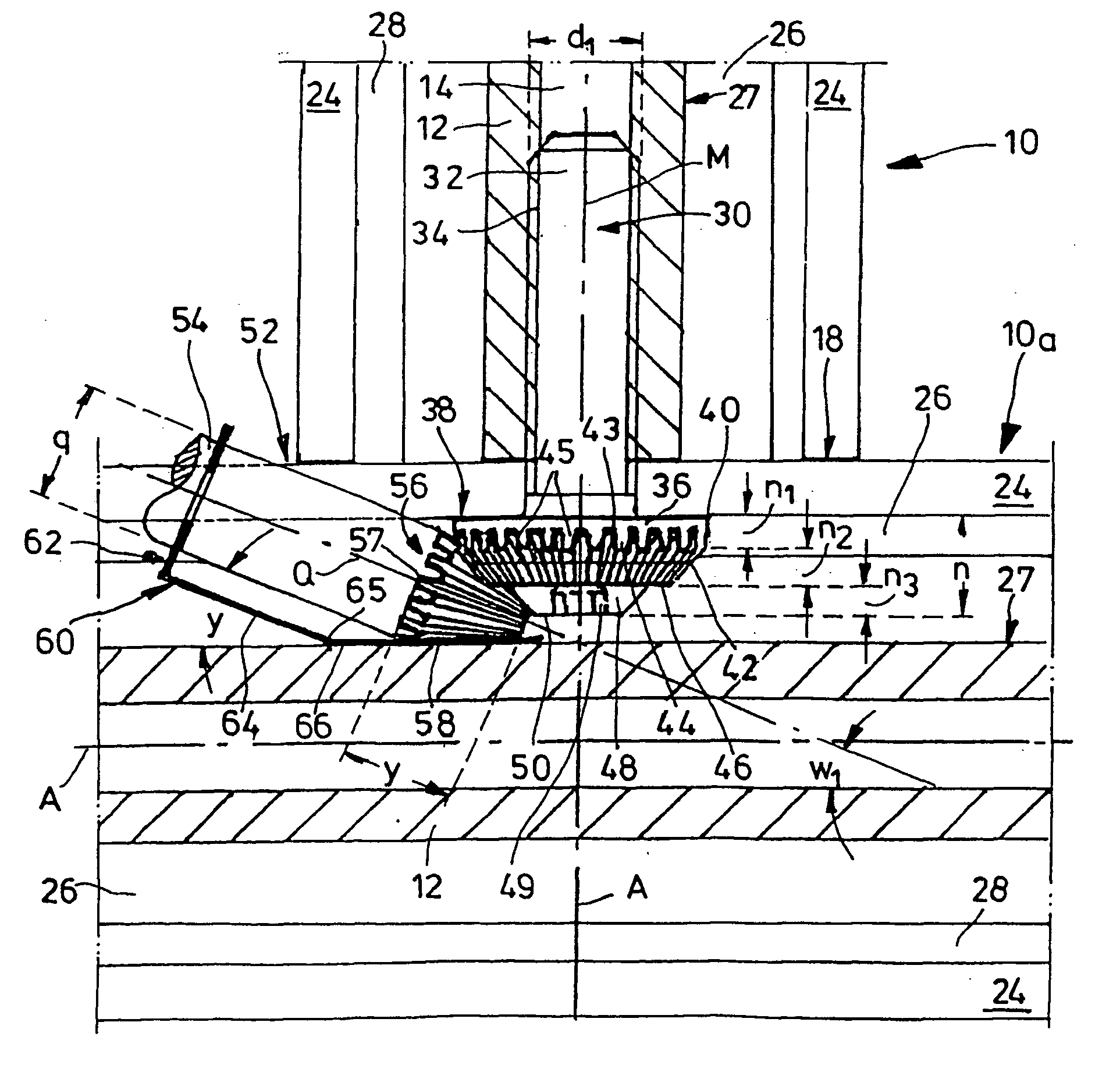
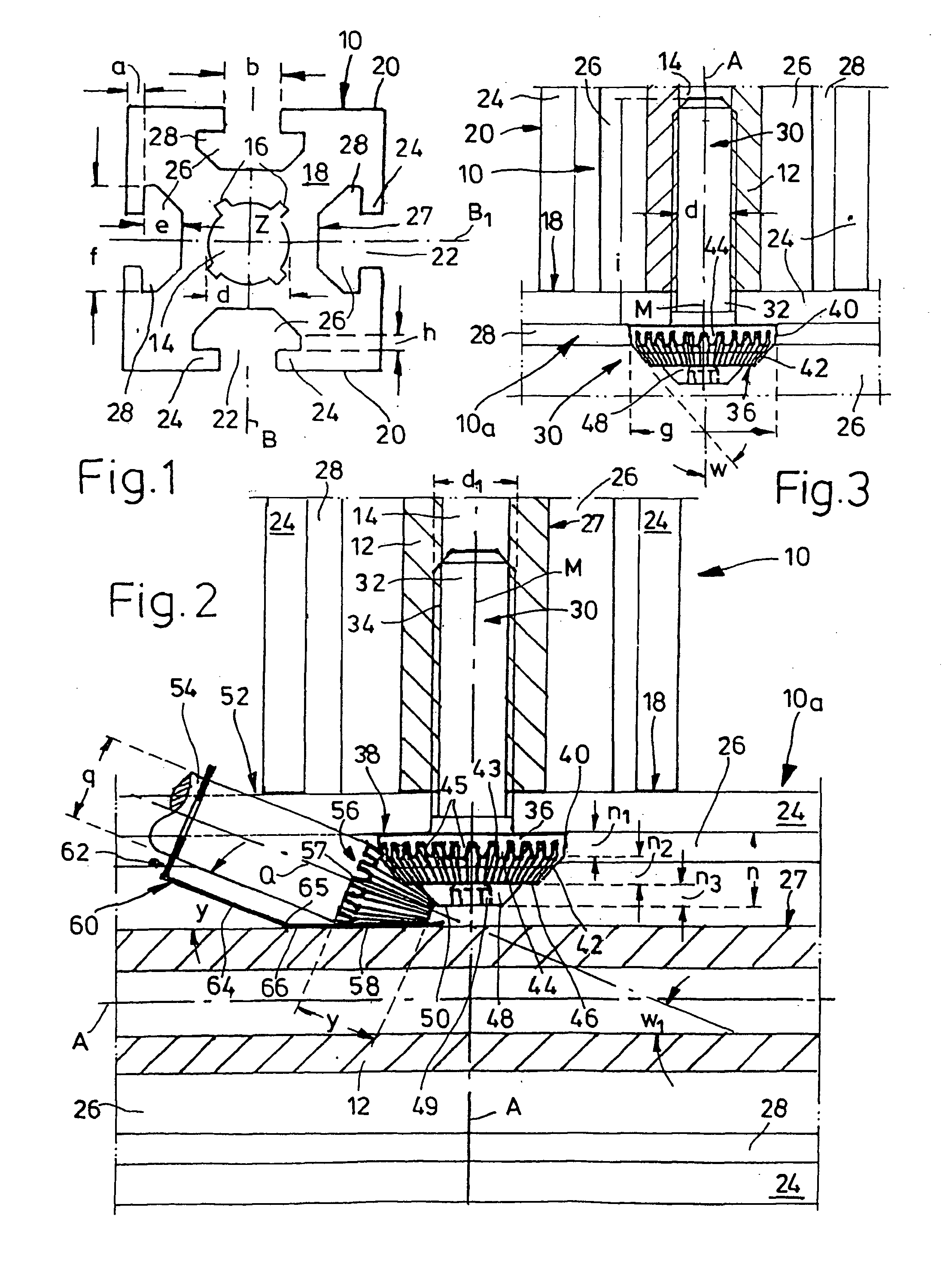
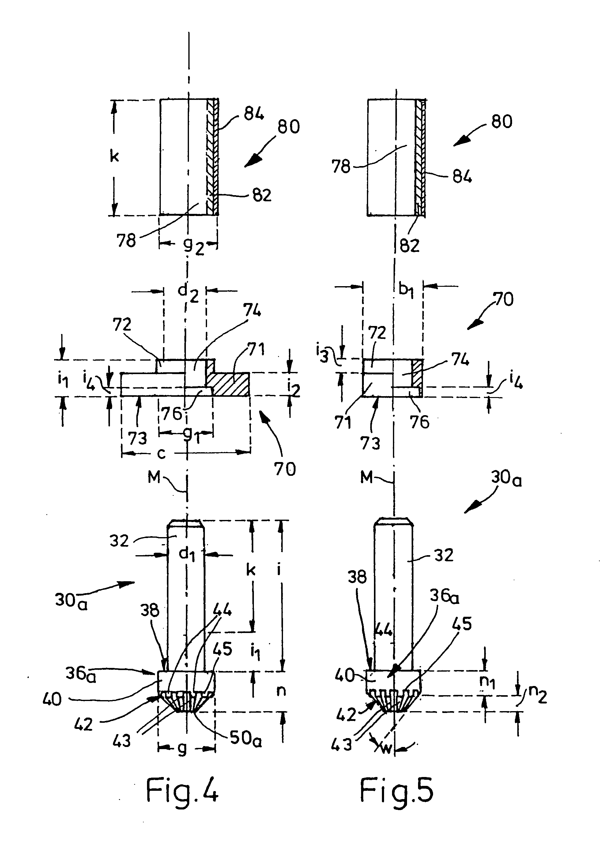
[0008] According to a further feature of the invention, the screw head should have, between a shaft-facing connection surface and the inclined wall surface, an annular section of constant diameter in which the shaft-facing ends of the grooves or notches form a crenellated edge pattern. The inclined wall surface should end at the head surface of the screw head or—in another embodiment—at a radial step surface, which latter surrounds in an annular manner an integrally formed top body. This tooth-free or notch-free end section is supported on the groove bottom when screwed on, and ensures a mating hold.
[0013] It has proven advantageous to make the diameter of the round profile shorter than the depth of the groove space of the hollow profile, in order to make it possible to insert the tool into the groove space.
[0014] Moreover, the angle between the axis of the round profile and the peripheral or outer surface of the insertion head should be approximately 20° to 40°, in particular approximately 25°. This likewise facilitates insertion of the tool, the grooves of which are to receive the ribs of the screw head on the connecting screw.
[0016] By virtue of the embodiment according to the invention, there is no longer any need for special configuration or reworking of the hollow profile. The connecting screw is simply rotated into the core hole—coarse-pitch thread or self-cutting thread—of one hollow profile and then pushed into the end of the other hollow profile. It is also conceivable firstly to screw the aforementioned threaded sleeve into the core hole, so as to provide for example a steel coarse-pitch thread for screwing in the connecting screw or toothed screw. To reduce friction, the latter can be provided with a coating of lubricant to make it easier to screw in.
[0020] The dimensions for the screw and the screwdriver of course depend on the profiles to be connected. However, all compatible profiles can be connected by means of the same screw. The stability of the connection is sufficient for simple frames, protective fences, housings, etc. Securing against twisting of the profiles to be connected is provided if at least one groove is occupied by a flat element. The connection is extremely simple, fast and thus of course very cost-effective.
[0021] The tool is inserted close to said connecting bolt into the longitudinal groove which receives it, and its inclined insertion head is pushed in between the groove bottom and the screw head. When the ribs of said screw head mesh with the grooves of the tool, operation of the connecting bolt can readily be carried out. The inventor's aim is thus achieved in a particularly simple manner.

Problems solved by technology

The hollow profiles, which are usually extruded from an aluminium alloy, must therefore be reworked in a special way after they have been manufactured; the making of the radial openings is very complicated and considerably reduces the stability of the profile.

Method used


Image

  • Device comprising two hollow profiles that are held together by means of a connecting screw, and corresponding tool
  • Device comprising two hollow profiles that are held together by means of a connecting screw, and corresponding tool
  • Device comprising two hollow profiles that are held together by means of a connecting screw, and corresponding tool

Examples


Embodiment Construction

[0028] A hollow profile 10 of square cross section extruded from a light metal alloy, having cross-sectional axes B, B1 as axes of symmetry placed through the centre Z of its front face 18—said centre Z being defined by a profile channel 14 of circular cross section of diameter d which runs in its central profile body 12 in the profile longitudinal axis A and is provided with radial edge grooves 16—has in each case in the centre of its profile side surfaces 20 a longitudinal groove 22 having a width b of for example 8 mm, said longitudinal groove being delimited at both ends by shaped ribs 24 with a thickness a of in this case 4 mm and merging into an undercut groove space 26 towards the profile longitudinal axis A. Said groove space is a channel-like recess of approximately triangular cross section which is overlapped by said shaped ribs 24 and has a depth e determined from the groove bottom 27 of 10 mm and a maximum width f of 22 mm and provides an axial insertion track 28 of heig...


PUM


Abstract

A device comprising two hollow profiles which are arranged approximately at a right angle from each other and each of which is provided with a profiling channel that extends parallel to the longitudinal axis (A) of the profile and an undercut longitudinal groove in at least one lateral face of the profile, the longitudinal groove extending parallel to the profiling channel. The two hollow profiles are held together by a connecting screw whose shaft engages into the profiling channel of one hollow profile and whose screw head is mounted within an undercut longitudinal groove of the other hollow profile. The periphery of the screw head is provided with grooves or notches that run on planes extending from the longitudinal axis (M) of the shaft while forming ribs therebetween.

Description

BACKGROUND OF THE INVENTION [0001] The invention relates to a device comprising two hollow profiles arranged in a butt-jointed manner approximately at right angles to one another, each of which has a profile channel parallel to its profile longitudinal axis and also, in at least one profile side surface, an undercut longitudinal groove parallel to the profile channel, according to the preamble of the independent claim. The invention furthermore relates to a tool for operating the connecting bolt. [0002] Document DE 201 06 561 discloses a device for connecting a first profile bar to a second profile bar which bears with a front face against a longitudinal side of the first profile bar. These profile bars are provided with undercut longitudinal grooves along their longitudinal sides and contain a clamping screw with a screw head and a threaded shaft which can be fixed in the region of the screw head in the undercut longitudinal groove of the first profile bar and can be screwed with i...

Claims


Application Information

Patent Timeline
IPC IPC(8): B25G3/00B25B15/00F16B7/18F16B35/06
CPCB25B15/005F16B7/187F16B35/06Y10T403/4681Y10T403/7117Y10T403/73Y10T403/1674Y10T403/556F16B2200/403F16B2200/67
Inventor STAUSS, ULRICH
Owner STAUSS ULRICH
Learn More