Pilot drill, step drill, and drill set for dental implant technology

a technology of dental implants and drill sets, which is applied in the field of pilot drills, step drills, and drill sets for dental implants, can solve the problems of many drilling instruments and working steps, multiplicity of instruments, and high cost of 3-stage milling cutters

Inactive Publication Date: 2006-09-21
THOMMEN MEDICAL
View PDF4 Cites 110 Cited by
  • Summary
  • Abstract
  • Description
  • Claims
  • Application Information

AI Technical Summary

Benefits of technology

[0022] The following features represent advantageous embodiments of the invention: the drill neck with the bevel is formed in a weakly cutting manner. The pilot guide has a length in the range from 1.0 mm to 4.0 mm, for example 3.0 mm. The pilot drill is preferably formed with two cutting edges and consequently has two tip cutting edges, two chamfers, two guide cutting edges, two spiral grooves, two bevels and two step cutting edges. The drill neck has a length at least equal to the depth of insertion of the implants to be applied. The pilot guide has a diameter in the region of 1.5 mm and the drill neck has a diameter in the region of 2.0 mm. The tip angle lying between the tip cutting edges is less than 90°; it preferably lies in the region of 80°. The spiral grooves extent continuously from the coronal end of the drill neck into the pilot tip, the spiral grooves having at the pilot tip only a fraction of their full cross section, as present at the drill neck, as a result of the smaller diameter. A number of visible depth markings are provided at equal or unequal intervals on the drill neck for checking the depth of penetration of the pilot drill.
[0023] The pilot guide with the pilot tip is intended for fixing the position of the step bore to be produced with the introduction of a start of a pilot bore through the cortical bone of the jawbone, the start comprising a pilot bore guide and a pilot bore tip. The step is intended for generating a noticeably increased drilling resistance once the cortical bone is penetrated—with completion of the pilot bore guide and tip—, so that this indication allows a surgeon to check the drillling direction that has been set up. The blunt guide cutting edges make it possible to correct the drilling direction within a conical range of correction without widening the pilot bore guide. The drill neck with its dimensioning is intended to create the pilot bore with the final depth.
[0025] The following features represent advantageous embodiments of the invention: the drill neck with the bevel is formed in a weakly cutting manner. The step guide has a length in the region of 2.0 mm. The step drill is preferably formed with three cutting edges and consequently has three tip cutting edges, three chamfers, three guide cutting edges, three spiral grooves, three bevels and three step cutting edges. The drill neck has a length at least equal to the depth of insertion of the implant to be applied. The step guide of different step drills, that is the first, second and third step drills, has a diameter in the region of 2.0 mm, 2.8 mm and 3.5 mm, respectively, and the drill neck of these first, second and third step drills has the associated diameter in the region of 2.8 mm, 3.5 mm and 4.3 mm, respectively. The tip angle formed between the tip cutting edges is greater than 90°; it preferably lies in the region of 120°.

Problems solved by technology

This has the consequence that many drilling instruments and working steps are necessary.
Here, too, this leads to a multiplicity of instruments and, moreover, 3-stage milling cutters are much more expensive.
All the drill systems presented require more working steps—drilling operations and drill changes—as different drill diameters are to be provided, which causes an increased time requirement, complicates the operational procedure, requires a relatively great number of different instruments and also increases the risk of mistakes.

Method used


Image

  • Pilot drill, step drill, and drill set for dental implant technology
  • Pilot drill, step drill, and drill set for dental implant technology
  • Pilot drill, step drill, and drill set for dental implant technology

Examples


Embodiment Construction

[0077] The following statement applies to the entire further description: where reference numerals are contained in a figure to clarify the drawing but are not explained in the directly associated text of the description, reference is made to where they are mentioned in previous descriptions of figures. In the interest of overall clarity, components are not usually designated by reference numerals repeatedly in the same figures or in subsequent figures if it is clearly evident from the drawing that they are “recurrent” components.

FIGS. 1A and 1B

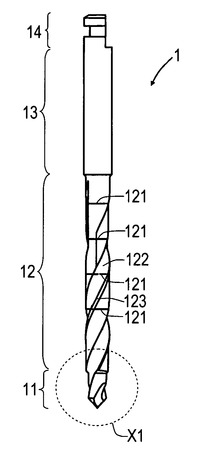
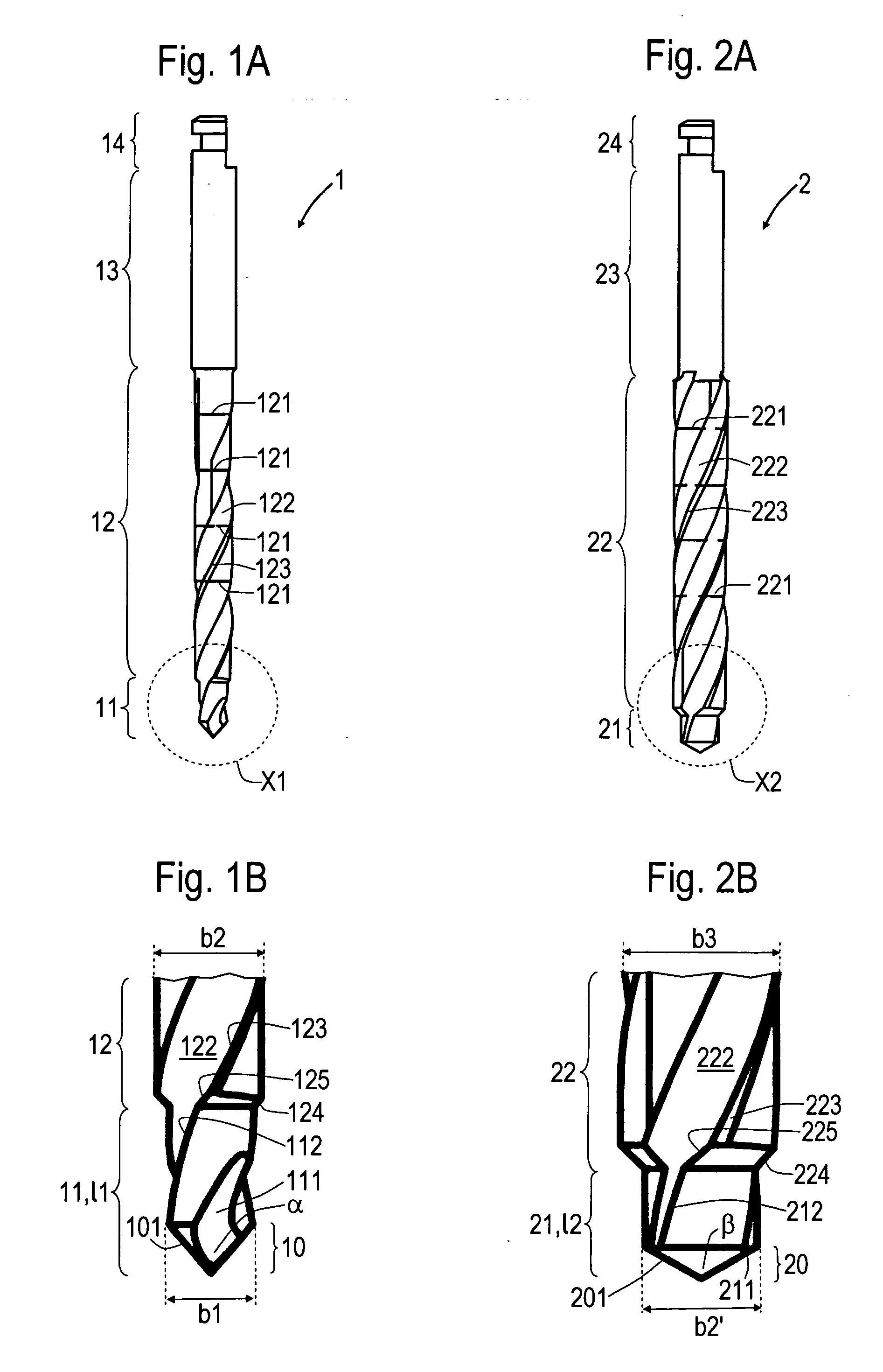
[0078] The pilot drill 1 serves for the preparation of a step bore in the form of a blind hole, to be introduced into a jawbone, for receiving a dental implant. At the apical end of the pilot drill 1 there is the pilot tip 10, with the tip cutting edges 101 arranged on it, which form the tip angle α. A pilot guide 11 extends from the pilot tip 10 in the direction of the coronal end of the pilot drill 1. Lying above the pilot guide 11 is the ...


PUM


Abstract

The invention relates to a pilot drill (1) for producing a pilot bore in a human jaw bone in preparation for its enlargement into a step bore, achieved by means of a first step drill (2) or if the step bore is further enlarged, by means of second and third step drills (2). The prepared step bore is designed to receive a dental implant, preferably in screw form. The pilot drill (1) and the first step drill (2) form a drill set. The pilot guide (11) on the pilot drill (1), comprising a step (124) lying in the transition region leading to the drill neck (12), positions the drill at the commencement of drilling in the corticalis, whereby the drilling direction can be corrected prior to the continued drilling down to the maximum depth of the pilot bore. The pilot guide (11) has a drill diameter (b1), whereas the step (124) leads into an enlarged drill diameter (b2). The step guide (21) of the first step drill (2) has a drill diameter (b2′) that corresponds to the drill diameter (b2). The drill diameter (b3) at the drill neck (22) of the first step drill (2) corresponds to the drill diameter at the step guide (21) of the second step drill (2). The second step drill corresponds in a similar manner to the third step drill (2). The advantages of the invention are that it requires a reduced number of drilling tools, that the implant bed can be prepared in a precise, gentle manner and that the inserted implants achieve a primary stability.

Description

FIELD OF APPLICATION OF THE INVENTION [0001] The present invention relates to a pilot drill, a step drill and a drill set formed by them for use in dental implantology. The pilot drill serves for producing a pilot bore in the form of a blind hole, to be introduced into a human jawbone as preparation for its enlargement into a step bore, which takes place with a different step drill or—if the step bore is to be enlarged further—with a number of different step drills. The prepared step bore is intended for receiving a dental implant, preferably in the form of a screw. In the case of implants in the form of screws, the prepared borehole can be provided with an internal thread before application or the implant is self-tapping, whereby the internal thread is cut into the jawbone as the implant is screwed in. The present invention relates primarily to dental implants in the form of screws. When it has become incurporated, the implant forms the anchorage for a superstructure to be built up...

Claims


Application Information

Patent Timeline
Patent Type & Authority Applications(United States)
IPC IPC(8): A61C3/02A61C8/00A61B17/16A61B17/17
CPCA61B17/1673A61B17/176A61C8/0089
Inventor STOOP, HANS
Owner THOMMEN MEDICAL
Why Eureka
Try Eureka