Process connection for process diagnostics

Active Publication Date: 2006-09-21
ROSEMOUNT INC
View PDF64 Cites 4 Cited by
  • Summary
  • Abstract
  • Description
  • Claims
  • Application Information

AI Technical Summary

Benefits of technology

[0006] A process coupling for coupling a diagnostic device to process fluid of an industrial process includes a process interface configured to physically couple to the process fluid. A fluid pathway extending from the

Problems solved by technology

If a process device (a process variable transmitter or a process controller) fails or is otherwise not operating within its specifications, the process being controlle

Method used


Image

  • Process connection for process diagnostics
  • Process connection for process diagnostics
  • Process connection for process diagnostics

Examples


Embodiment Construction

[0014] The present invention provides techniques for coupling process devices to industrial process fluids in a manner which improves the devices' sensitivity to process noise or a subset of interest, in order to enhance the diagnostic capabilities of the device. This may include amplification and / or suppression of all or part of the process noise signal.

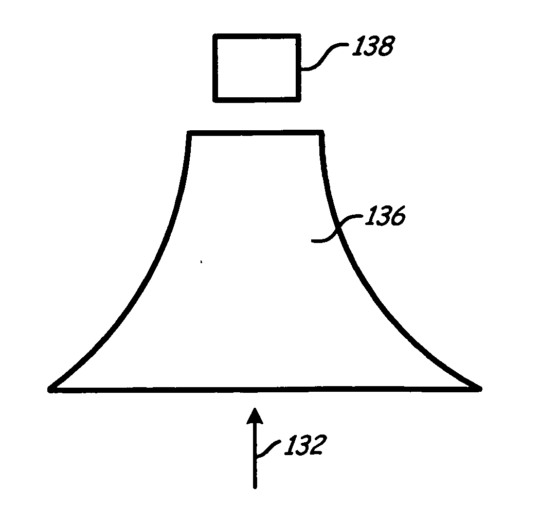
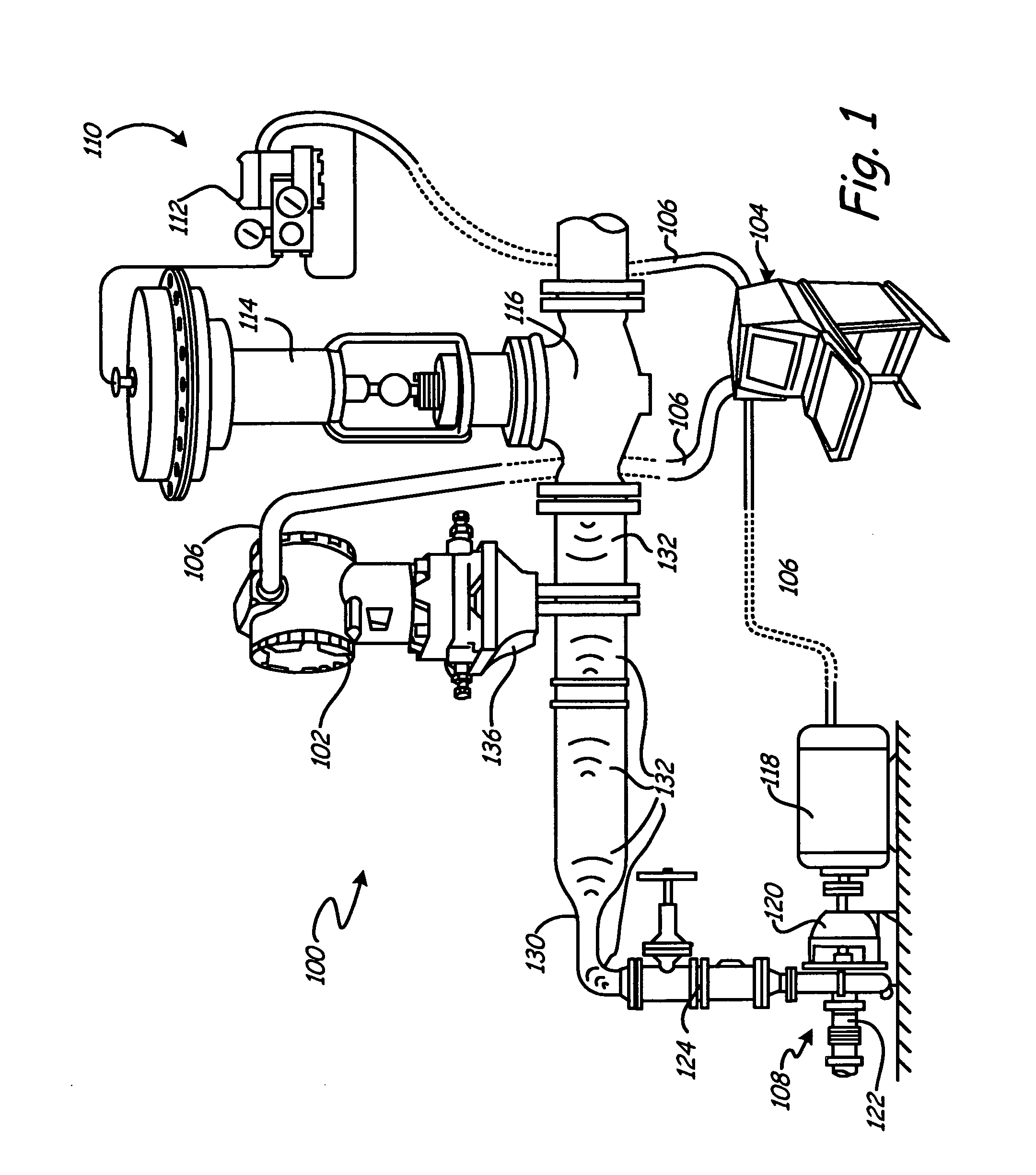
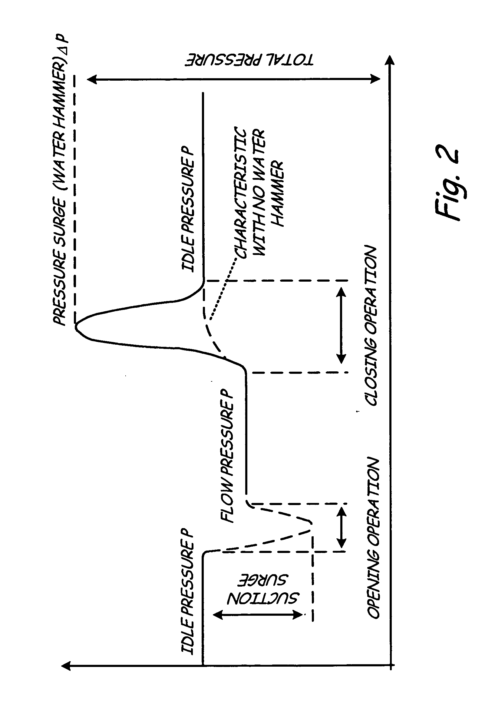
[0015] In FIG. 1, a typical environment for a diagnostic device 102 in accordance with one embodiment of the invention is illustrated at 100. In FIG. 1, diagnostic device 102, such as a process transmitter 102 configured as a pressure transmitter, is shown connected to control system 104. Process transmitters can be configured to monitor one or more process variables associated with fluids in a process plant such as slurries, liquids, vapors and gasses in chemical, pulp, petroleum, gas, pharmaceutical; food and other fluid processing plants. The monitored process variables can be pressure, flow, level, temperature or other properti...


PUM


Abstract

A process coupling for coupling a diagnostic device to process fluid of an industrial process includes a process interface configured to physically couple to the process fluid. A fluid pathway extending from the process interface configured to couple a process interface element of the process device to the process fluid. The fluid pathway is configured to optimize transmission of process noise from the process fluid to the process device for use by the diagnostic device.

Description

CROSS-REFERENCE TO RELATED APPLICATION [0001] The present application is based on and claims the benefit of U.S. provisional patent application Ser. No. 60 / 656,994, filed Feb. 28, 2005, the content of which is hereby incorporated by reference in its entirety.BACKGROUND OF THE INVENTION [0002] The present invention relates to industrial process control and monitoring systems. More specifically, the present invention relates to diagnostics used in such systems. [0003] Industrial process control and monitoring systems are used to monitor or control many types of industrial processes. For example, monitoring systems can be used to monitor the transfer of process fluids, such as oil, gasoline, etc., while industrial process control systems are used to control industrial processes. For example, a process transmitter such as a pressure transmitter can be configured to sense a process pressure and transmit information related to the sensed pressure to a remote location, such as a control ro...

Claims


Application Information

Patent Timeline
IPC IPC(8): G05B11/01G05B13/02
CPCG05B23/0208
Inventor HEDTKE, ROBERT C.BRODEN, DAVID A.
Owner ROSEMOUNT INC
Why Eureka
Try Eureka