Low-cost heat pump water heater

a low-cost, water heater technology, applied in heat pumps, refrigerating machines, lighting and heating apparatus, etc., can solve the problems of inactivity of desuperheaters, and inability to meet the water heating load in the house, etc., to achieve optimal and efficient design

Inactive Publication Date: 2006-09-28
UT BATTELLE LLC
View PDF28 Cites 30 Cited by
  • Summary
  • Abstract
  • Description
  • Claims
  • Application Information

AI Technical Summary

Benefits of technology

[0011] The invention comprises a simple method (geometric twisted sleeve) for arranging the internal condenser by adjusting the number of coils, pitch, radius and location within the tank to affect...

Problems solved by technology

.); however the small market that was present is drying up due to high costs based on old technologies.
HPWHs are also manufactured and sold in Asia and Australia at low volumes due to high first costs.
One problem with a desuperheater HPWH is that the house space conditioning load is usually not in sync with the water heating load.
That is, when hot water is needed, the house might not need cooling or heating, the desuperheater is therefore inactive, and water heating is provided by inefficient, backup electric resistance water heaters.
This type of HPWH is bulky, requires a water pump, and its ...

Method used


Image

  • Low-cost heat pump water heater
  • Low-cost heat pump water heater
  • Low-cost heat pump water heater

Examples


Embodiment Construction

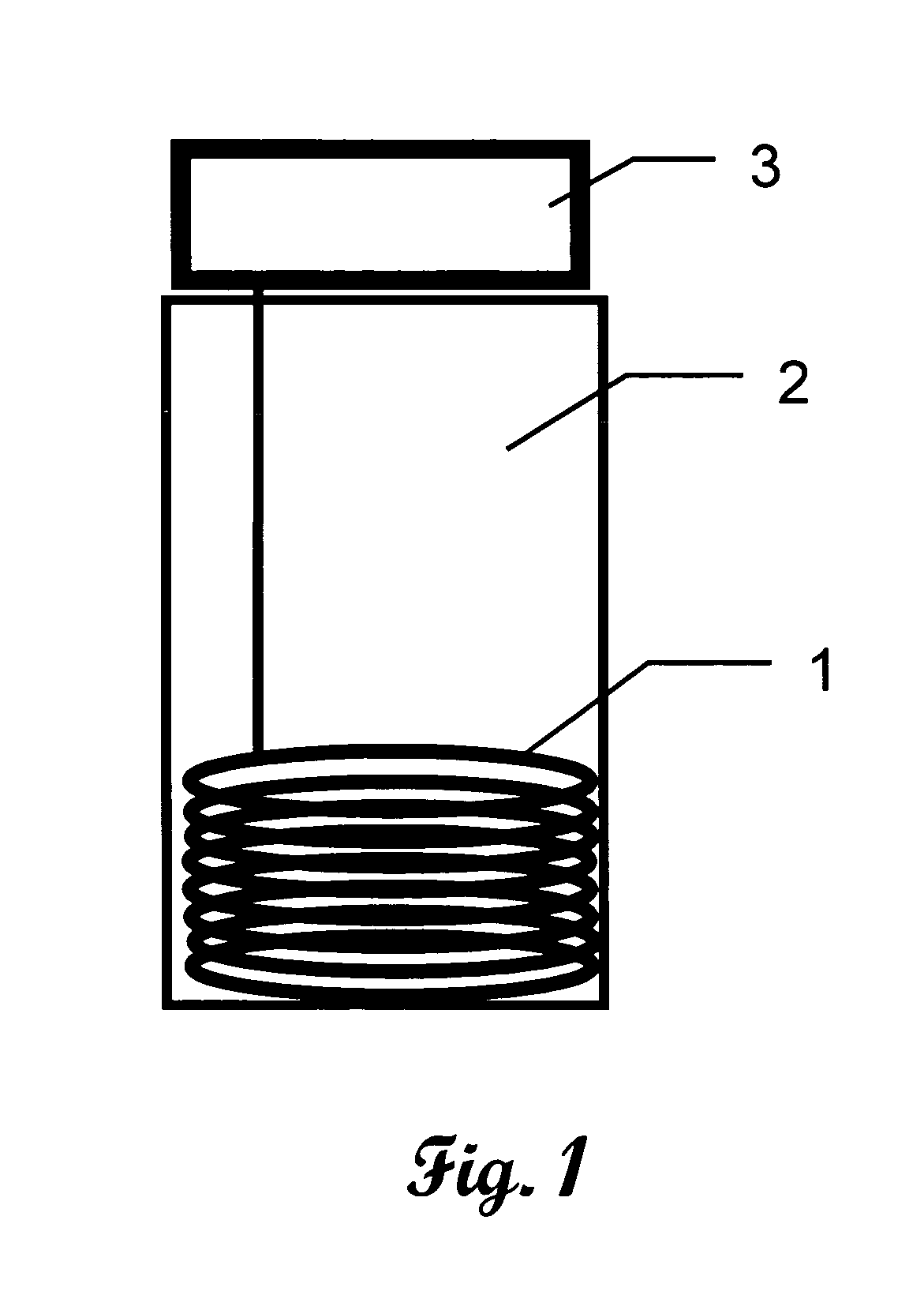
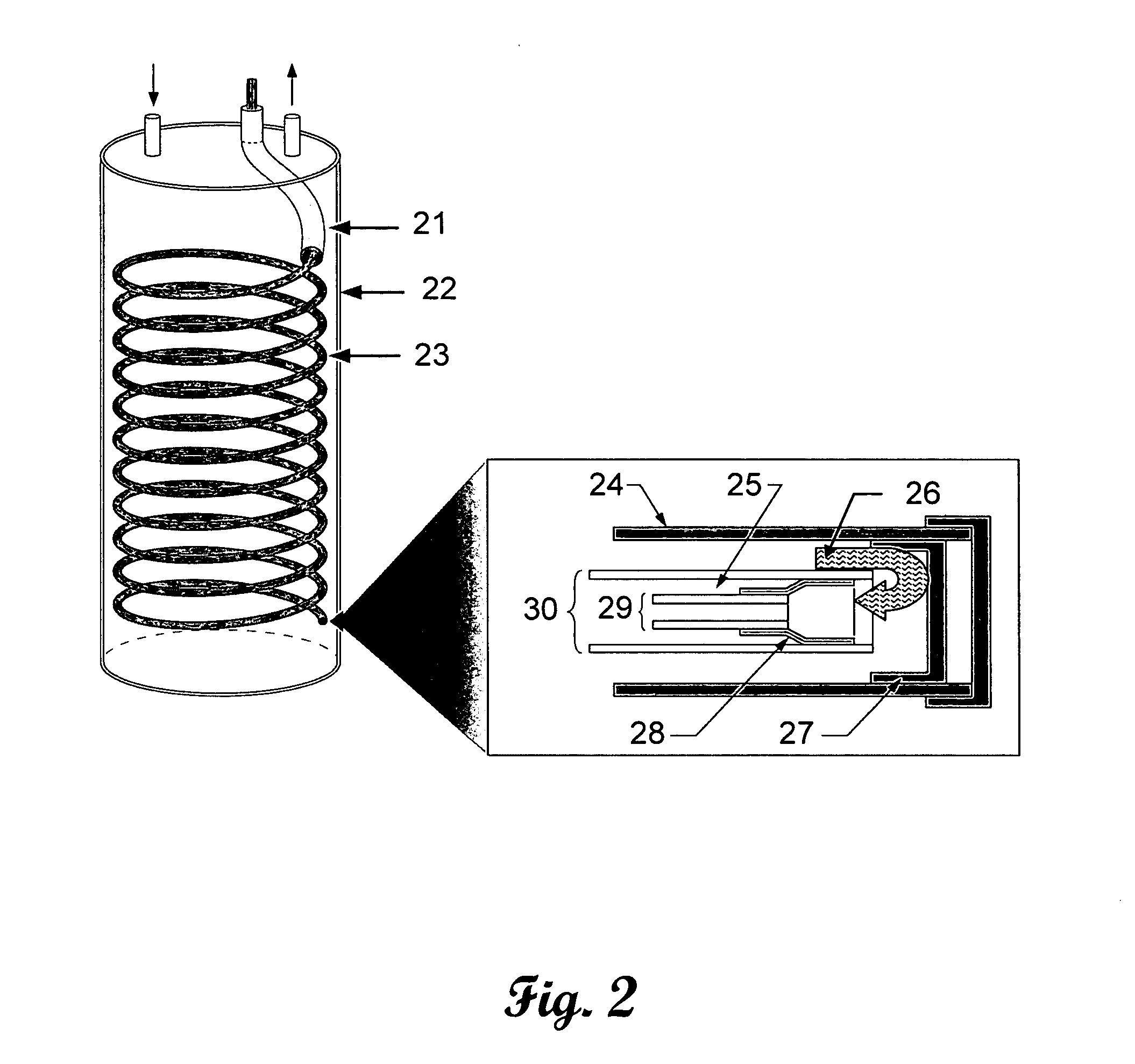
[0022] One of the biggest challenges to be met is finding a way to install a large surface area condenser into the conventional tank through one of the small pipe fittings (¾″ FPT) that is already on the top of all water heaters. This is somewhat akin to building a ship in a bottle with a small neck. The invention overcomes this problem by installing a short, geometric twisted sleeve through the small diameter top fitting in the top of the tank, and then pushing a long condenser assembly through the open sleeve. As the linear condenser is pushed through the sleeve, it forms itself into a helix inside the tank. The radius, pitch and location of the helix inside the tank is pre-determined by the geometry of the sleeve. Calculations show that a 5 / 16-in diameter condenser can be pushed through a ¾-inch, sleeved hole in a tank, and that a 50-foot long condenser section, 5 / 16-in diameter, will form a helical condenser inside the tank providing more than 4 sq. ft. of condenser surface insi...


PUM


Abstract

An improved heat pump water heater of the type having a water tank with an exterior surface and defining a water chamber, a top on the water tank with at least one opening therethrough in communication with the water chamber, and a heat pump of the type having a compressor, the compressor being in fluid communication with an annular condenser assembly via a first refrigerant conduit, the annular condenser assembly being in fluid communication with an expansion device through a second refrigerant conduit, the expansion device being in fluid communication with an evaporator through a third refrigerant conduit, the evaporator being in fluid communication with the compressor through a fourth refrigerant conduit and control means therefore, the improvement comprising disposing the annular condenser assembly through the opening in the top of the water tank and into the water chamber, the water tank opening further comprising a geometric twisted sleeve positioned to form a helical insertion pattern in the annular condenser assembly, the annular condenser assembly further comprising an elongate outer tube having a closed bottom end and an open and opposed upper end in flow communication with the first refrigerant conduit, an elongate return tube disposed within the outer tube and having an open bottom end and a closed and opposed top end in flow communication with the second refrigerant conduit, an elongate capillary tube disposed within the return tube and having an open bottom end and an open and opposed top end in flow communication with the second refrigerant conduit, and an air gap disposed between the capillary tube and the return tube.

Description

CROSS-REFERENCE TO RELATED APPLICATIONS [0001] This application claims priority to U.S. Provisional Patent Application 60 / 664,776 filed Mar. 24, 2005, and is herein incorporated by reference. This application is also related to U.S. Pat. No. 6,233,958, issued May 22, 2001, herein incorporated by reference in its entirety.STATEMENT REGARDING FEDERALLY SPONSORED RESEARCH [0002] This invention was made with United States Government support under Contract No. DE-AC05-00OR22725 between the United States Department of Energy and U. T. Battelle, LLC. The United States Government has certain rights in this invention.FIELD OF THE INVENTION [0003] This invention is in the general field of water heaters and specifically teaches a low-cost embodiment for a heat pump water heater. BACKGROUND OF THE INVENTION [0004] U.S. Pat. No. 5,946,927 teaches a “drop-in” heat pump water heater (HPWH), and ECR International produces a HPWH based around this patent. U.S. Pat. No. 6,233,958 teaches a HPWH with ...

Claims


Application Information

Patent Timeline
IPC IPC(8): F25B27/00
CPCF24H4/04F25B30/02
Inventor TOMLINSON, JOHN J.MEI, VIUNG C.
Owner UT BATTELLE LLC
Why Eureka
Try Eureka