Power transmission device for driving robot wrist and power transmission device

a technology of power transmission device and wrist, which is applied in the direction of mechanical control device, gearing, instruments, etc., can solve the problem of inability to form mounting holes, etc., and achieve the effect of good balance of rotation and high strength

Inactive Publication Date: 2006-09-28
SUMITOMO HEAVY IND LTD
View PDF13 Cites 17 Cited by
  • Summary
  • Abstract
  • Description
  • Claims
  • Application Information

AI Technical Summary

Benefits of technology

[0020] According to various exemplary embodiments of the present invention, it is unnecessary to use a separate joint flange in accordance with the attachment or the like or change design of the power transmission device and the like. Furthermore, the power transmission device that is compact, has a good balance of rotation, and has high strength can be designed.

Problems solved by technology

Therefore, when a mounting hole (e.g., a tap) is formed in the output flange of the power transmission device and the attachment or the like is mounted by means of a mounting screw or the like, if another member (e.g., the inner pin or the carrier bolt) is fitted into the output flange, it is inevitably necessary to form the mounting hole at a position other than a position of the other member.
In other words, for some types of attachment or the like to be mounted, the mounting hole cannot be formed while sufficient mounting strength is ensured.
Thus, in some cases, it is necessary to use a separate joint flange for connection, or a problem is caused that the power transmission device or a mounting portion of the attachment or the like to be mounted has to be redesigned.

Method used


Image

  • Power transmission device for driving robot wrist and power transmission device
  • Power transmission device for driving robot wrist and power transmission device
  • Power transmission device for driving robot wrist and power transmission device

Examples


Embodiment Construction

[0026] An exemplary embodiment of the present invention is now described with reference to the accompanying drawings. In the description and the drawings, components that are the same or similar as / to those in the aforementioned conventional example are labeled with reference numerals in which last two digits are the same as those in the conventional example, and the description of those components is omitted in an appropriate manner. That is, only a difference between the exemplary embodiments of the present invention and the conventional example is described.

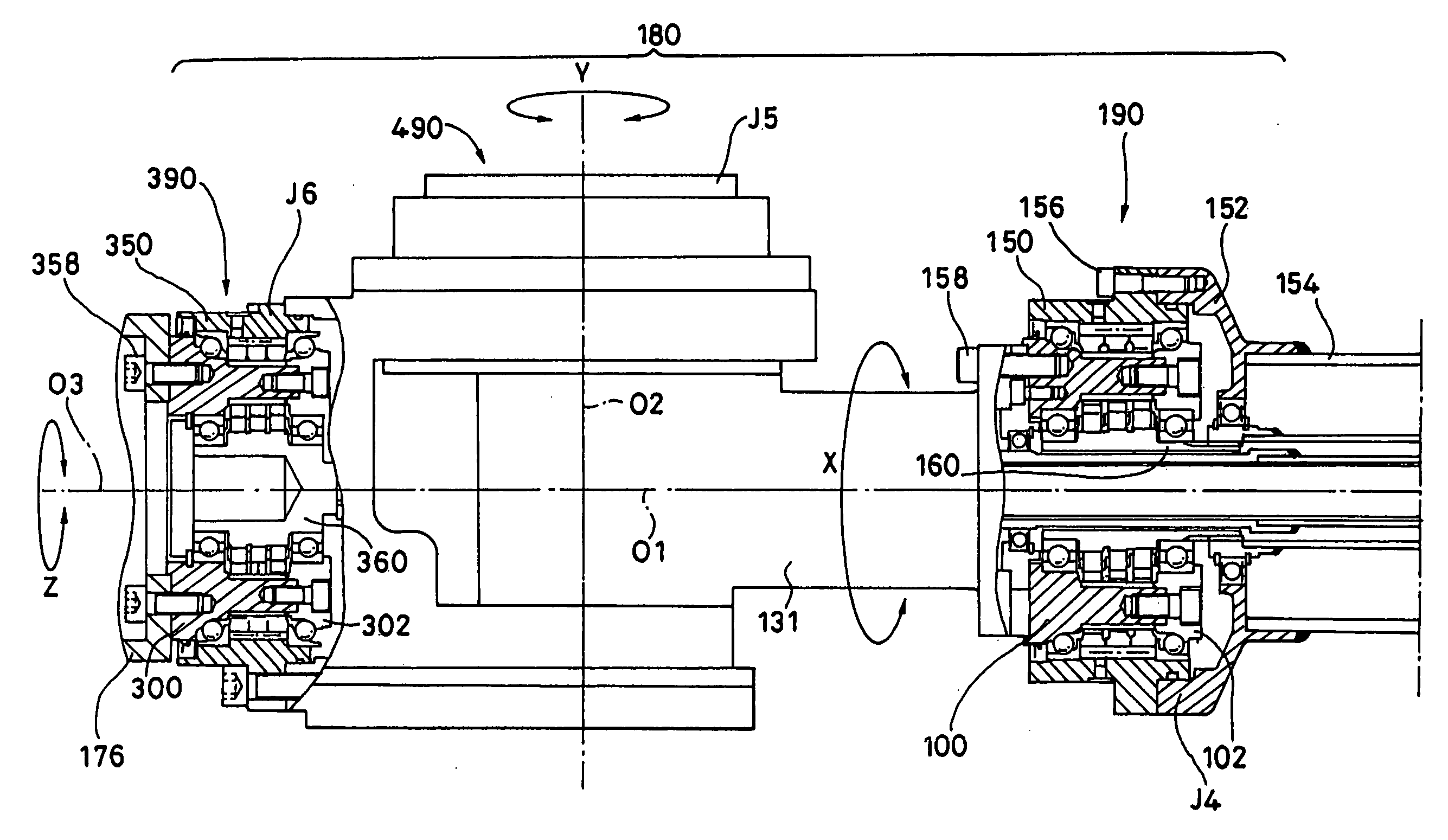
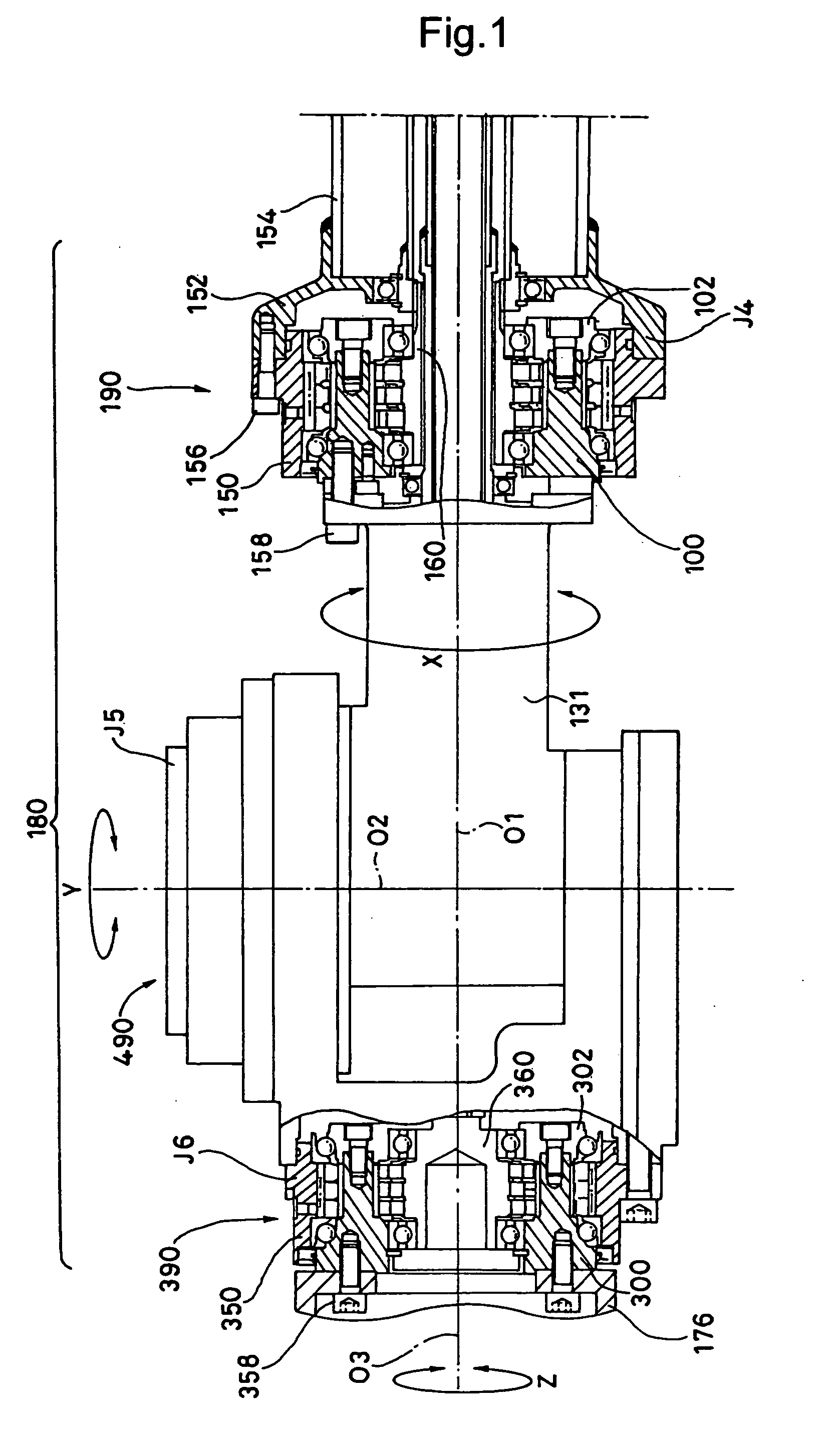
[0027]FIG. 1 is a partial cross-sectional view showing a whole power transmission device according to an exemplary embodiment of the present invention. The power transmission device is attached to a robot wrist. In the following description, the robot wrist means a portion including the fourth one of a plurality of axes included in a robot and all the following portions. More specifically, the robot wrist means a portion incl...


PUM


Abstract

The power transmission device includes an internal gear and an external gear that is inscribed in the internal gear and engages with the internal gear, and can transmit an input power to an attachment. The power transmission device further includes: an inner pin for bringing out a relative rotation component between the internal gear and the external gear; and an output flange connected to the inner pin. In this configuration, the inner pin and the output flange are integrally formed as one member, and a mounting hole for connecting the output flange to the attachment is formed in a surface of the output flange that is opposite to the inner pin.

Description

BACKGROUND OF THE INVENTION [0001] 1. Field of the Invention [0002] The present invention relates to a power transmission device. More particularly, the present invention relates to a power transmission device capable of transmitting an input power to a next-stage member (including an attachment), which can be suitably used for driving a robot wrist. [0003] 2. Description of the Related Art [0004] A power transmission device disclosed in Japanese Patent Laid-Open Publication No. 2002-61720 is conventionally known. This power transmission device has an output shaft in the shape of a flange and can be directly attached to a next-stage member (e.g., an attachment of an industrial robot). [0005]FIGS. 4A, 4B, and 4C show a power transmission device 290 having approximately the same structure as the aforementioned conventional power transmission device disclosed in Japanese Patent Laid-Open Publication No. 2002-61720. FIG. 4A is a front view of the power transmission device 290, FIG. 4B i...

Claims


Application Information

Patent Timeline
Patent Type & Authority Applications(United States)
IPC IPC(8): B25J18/00
CPCB25J9/102Y10T74/20305F16H1/32B25J17/0283Y10S901/19
Inventor HAGA, TAKASHITSURUMI, YOTAMENAGA, JUN
Owner SUMITOMO HEAVY IND LTD
Why Eureka
Try Eureka