Wabble plate type variable displacement compressor

a variable displacement, compressor technology, applied in the direction of positive displacement liquid engine, oblique crank gearing, gearing, etc., can solve the problems of insufficient vibration, noise and durability, accumulated play becomes great, and the contact pressure of specified balls may locally increase, so as to improve vibration and noise, improve the effect of vibration balance and silent performan

Active Publication Date: 2010-04-15
SANDEN CORP
View PDF3 Cites 3 Cited by
  • Summary
  • Abstract
  • Description
  • Claims
  • Application Information

AI Technical Summary

Benefits of technology

[0022]Thus, in the wabble plate type variable displacement compressor according to the present invention, as compared with the wabble plate rotation preventing mechanism using the conventional uniform motion joint, uniform and continuous contact of a plurality of balls operating for power transmission can be achieved, a rotation preventing mechanism small-sized, excellent in durability and silent performance, good in rotational balance, easy in machining and inexpensive can be realized, and a wabble plate type variable displacement compressor, having an excellent performance which has not been achieved by the conventional technologies, can be provided.
[0023]FIG. 1 is a vertical sectional view of a wabble plate type variable displacement compressor according to an embodiment of the present invention.
[0024]FIG. 2 is a vertical sectional view of the wabble plate type variable displacement compressor depicted in FIG. 1, showing an operational condition different from that depicted in FIG. 1.
[0025]FIG. 3 is an exploded perspective view of a main portion including a wabble plate rotation preventing mechanism of the wabble plate type variable displacement compressor depicted in FIG. 1.
[0026]FIG. 4 shows an example of the structure of the wabble plate type variable displacement compressor depicted in FIG. 1, FIG. 4(A) is a partial, vertical sectional view thereof, and FIG. 4(B) is a partial elevational view thereof.
[0027]FIG. 5 is a partial elevational view showing another example of the structure of the wabble plate type variable displacement compressor depicted in FIG. 1.

Problems solved by technology

In this structure, since wabble parts and a swash plate are supported by an outer ring of a Birfield type uniform motion joint provided as a wobble plate rotation preventing mechanism, and ultimately supported by a main shaft via a cage of an internal part of the uniform motion joint (a cage for regulating positions of a plurality of balls for performing power transmission), and further, via an inner ring of the uniform motion joint, the number of interposed parts increases and the accumulated play becomes great, and therefore, there is a problem insufficient in vibration, noise and durability.
Further, although the Birfield type uniform motion joint disclosed in Patent documents 1, 3 and 4 theoretically has a structure performing a rotational power transmission between inner and outer rings by a plurality of balls, actually it is a multiple restriction structure, and it is difficult to achieve uniform and continuous contact of the plurality of balls, and therefore, a contact pressure of specified balls may locally increase.
Therefore, in order to ensure a sufficient transmission ability, it is necessary to employ a sufficiently large ball size (ball diameter), and from these reasons, it is difficult to make the structure further small-sized, and it is difficult to apply it to a small displacement compressor.
Further, since the support for the rotational main shaft of the compressor in the internal mechanism described in Patent documents 2, 3 and 4 is provided on one side relative to the main mechanism portion (a cantilever supporting is employed), whirling of the main shaft becomes great, and it is disadvantageous on durability, vibration and noise.
Further, in the compression mechanism disclosed in Patent documents 3 and 4, since the inner ring of the uniform motion joint is supported slidably in the axial direction at a condition being prevented with rotation, it is necessary to make the main shaft thick in order to ensure the rigidity of the main shaft provided to the housing to be sufficiently great, and it may cause increase of the weight of the main shaft and the weight of the product.
Further, in the uniform motion joint mechanism disclosed in Patent documents 3 and 4, machining of grooves for regulating the positions of a plurality of balls operating for power transmission is complicated, and the mechanism may be disadvantageous on cost.
Furthermore, in the compression mechanism disclosed in Patent document 2, since there is no support in the radial direction due to the main shaft in the main mechanism portion and play in the wabble portion in the radial direction tends to become great, by this play, problems on durability, vibration and noise may occur.Patent document 1: U.S. Pat. No. 5,112,197Patent document 2: U.S. Pat. No. 5,509,346Patent document 3: U.S. Pat. No. 5,129,752Patent document 4: JP-A-2006-200405

Method used


Image

  • Wabble plate type variable displacement compressor
  • Wabble plate type variable displacement compressor
  • Wabble plate type variable displacement compressor

Examples


Embodiment Construction

[0077]Hereinafter, desirable embodiments of the present invention will be explained referring to figures.

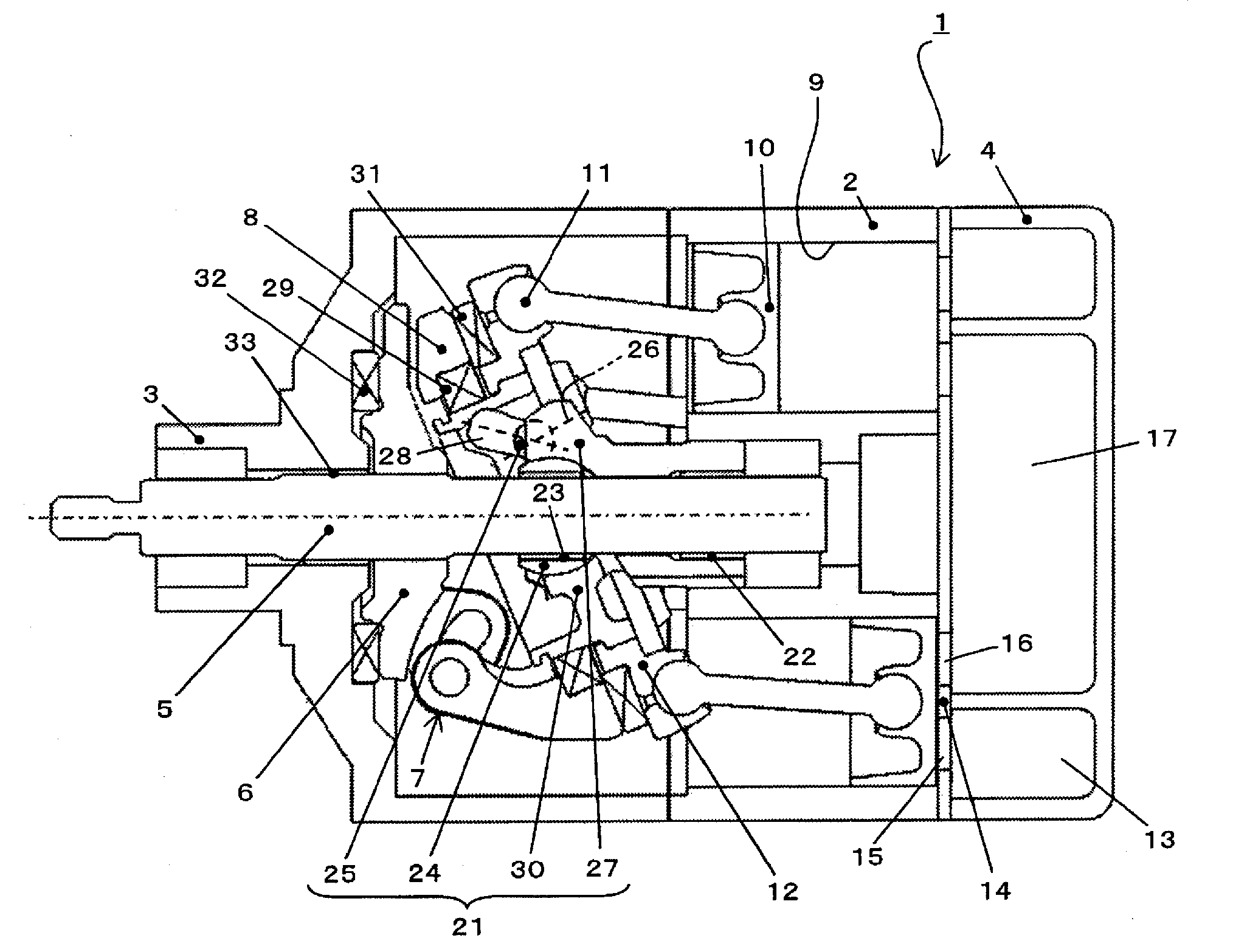
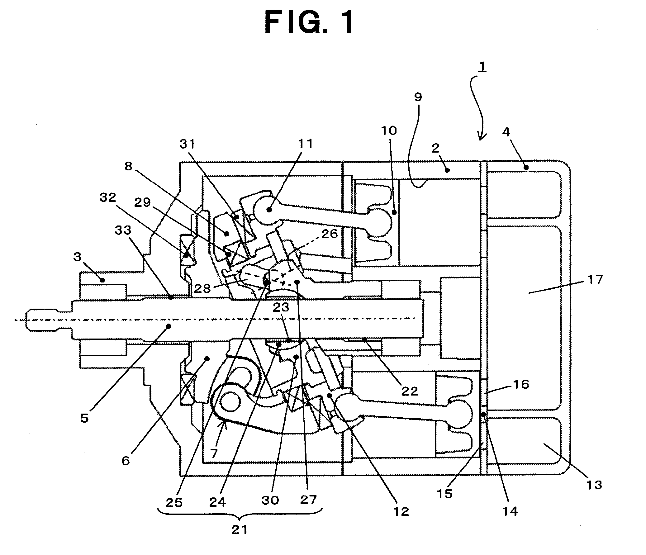
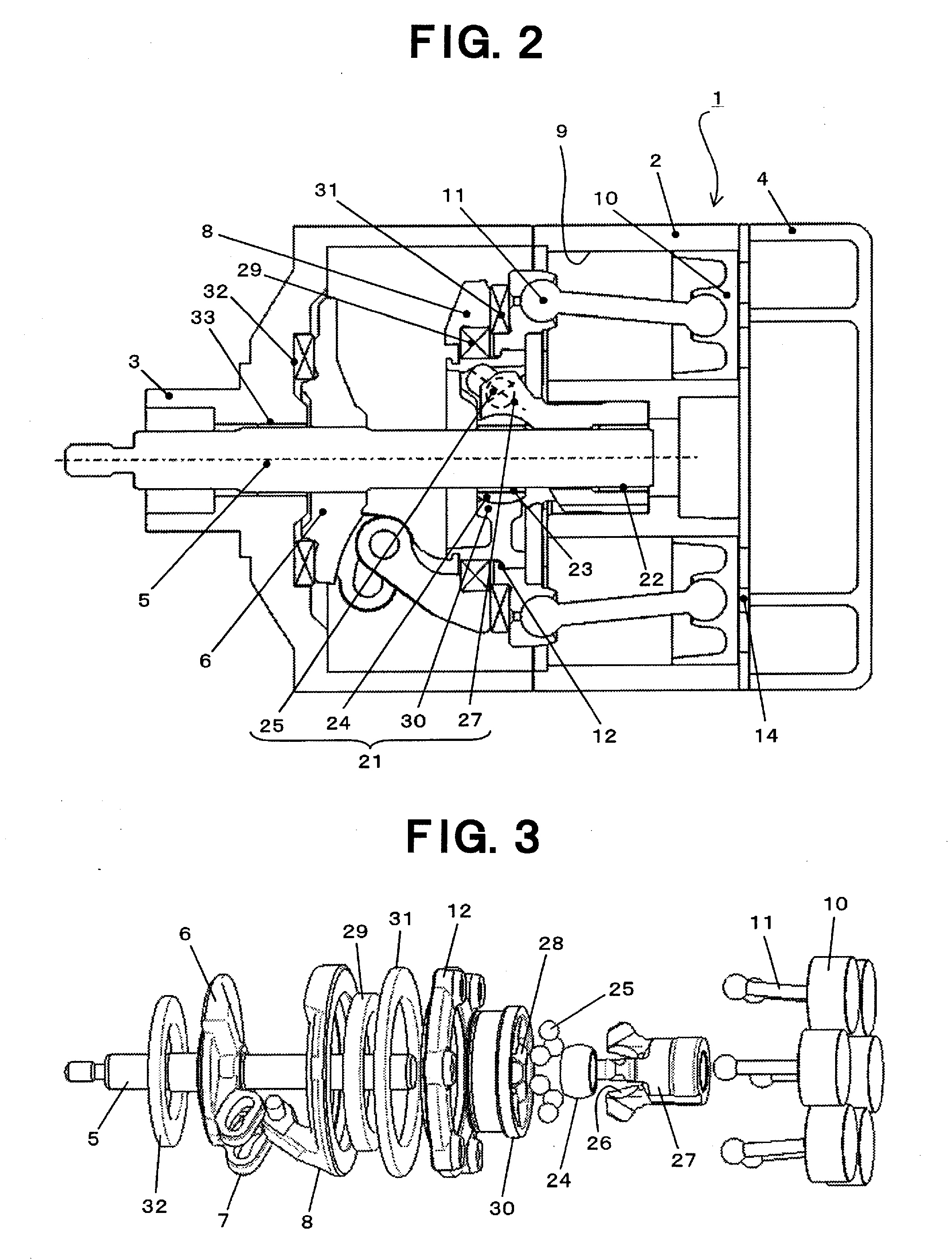
[0078]FIG. 1 shows a wabble plate type variable displacement compressor according to an embodiment of the present invention, and shows its entire structure in the operation state at the condition of the displacement achieving its maximum discharge. FIG. 2 shows the operation state of the wabble plate type variable displacement compressor depicted in FIG. 1 at the condition of the displacement achieving its minimum discharge. FIG. 3 shows a main portion including a wabble plate rotation preventing mechanism in the wabble plate type variable displacement compressor depicted in FIG. 1 as an exploded perspective view.

[0079]In FIGS. 1 and 2, a wabble plate type variable displacement compressor 1 has a housing 2 disposed at the central portion, a front housing 3 and a rear housing 4 disposed on both sides of the housing 1 as its housings, and a rotational main shaft 5 inputted with a r...


PUM


Abstract

A wabble plate type variable displacement compressor comprises a rotation preventing mechanism of the wabble plate which includes (a) an inner ring provided movably in the axial direction although rotation is prevented, supporting a main shaft at the inner diameter portion to rotate relatively and to move relatively in the axial direction and having a plurality of guide grooves for guiding a plurality of balls provided for power transmission, (b) a sleeve functioning as a wabble central member of wabble movement of the wabble plate, provided on the main shaft to rotate relatively thereto and to move in the axial direction and engaging with the inner ring movably in the axial direction, (c) an outer ring having a plurality of guide grooves for guiding balls at positions opposing respective guide grooves in the inner ring, supported on the sleeve wabblingly, supporting the wabble plate fixedly on the outer circumference and supporting a swash plate rotatably via a bearing, and (d) a plurality of balls held by the guide grooves formed in the inner ring and the outer ring and being compressed between the guide grooves to transmit power. While play in a uniform motion joint provided as the wabble plate rotation preventing mechanism in the radial direction and the rotational direction is suppressed, uniform and continuous contact of the plurality of balls operating for power transmission can be realized, and a compact, easy-to-machine and inexpensive wabble plate type variable displacement compressor exhibiting good durability and silent performance can be provided.

Description

TECHNICAL FIELD OF THE INVENTION[0001]The present invention relates to a wabble plate type variable displacement compressor, and specifically, to a wabble plate type variable displacement compressor which incorporates therein a new rotation preventing mechanism for the wabble plate.BACKGROUND ART OF THE INVENTION[0002]A wabble plate type variable displacement compressor is known wherein a rotational movement of a swash plate rotated together with a rotational main shaft and supported changeably in angle relative to the main shaft is converted into a wabble movement of a wabble plate, and by transmitting the wabble movement to a piston connected to the wabble plate, the piston is reciprocated. In this wabble plate type variable displacement compressor, because it is necessary to prevent the rotation of the wabble plate connected to the piston, a rotation preventing mechanism of the wabble plate is incorporated. With respect to the rotation preventing mechanism of the wabble plate, va...

Claims


Application Information

Patent Timeline
Patent Type & Authority Applications(United States)
IPC IPC(8): F04B27/18F04B27/22
CPCF04B27/1063F04B27/1072F16H23/04F04B27/18F04B27/1081
Inventor TAGAMI, SHINJI
Owner SANDEN CORP
Why Eureka
Try Eureka