Double tube hydraulic shock absorber

Active Publication Date: 2006-09-28
KYB CORP
View PDF8 Cites 9 Cited by
  • Summary
  • Abstract
  • Description
  • Claims
  • Application Information

AI Technical Summary

Benefits of technology

[0010] It is therefore an object of this invention to prevent a base valve of a double tube hydraulic shock absorber from buckling

Problems solved by technology

When the valve case 36 buckles, the non-return valve 37 and pressure side damping force-generating valve 38 disposed on the valve case 36 deviate from their predetermined positions, and as a result, it may be impossible to generate a desi

Method used


Image

  • Double tube hydraulic shock absorber
  • Double tube hydraulic shock absorber
  • Double tube hydraulic shock absorber

Examples


Embodiment Construction

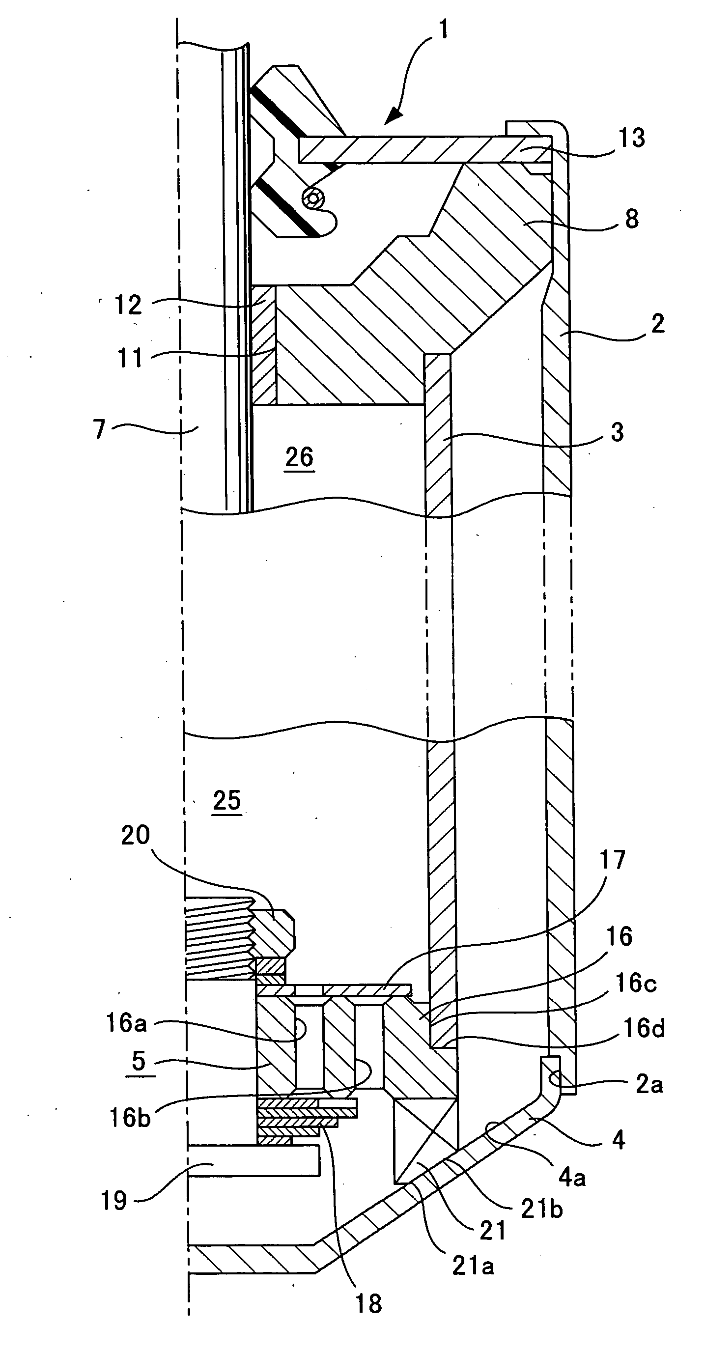
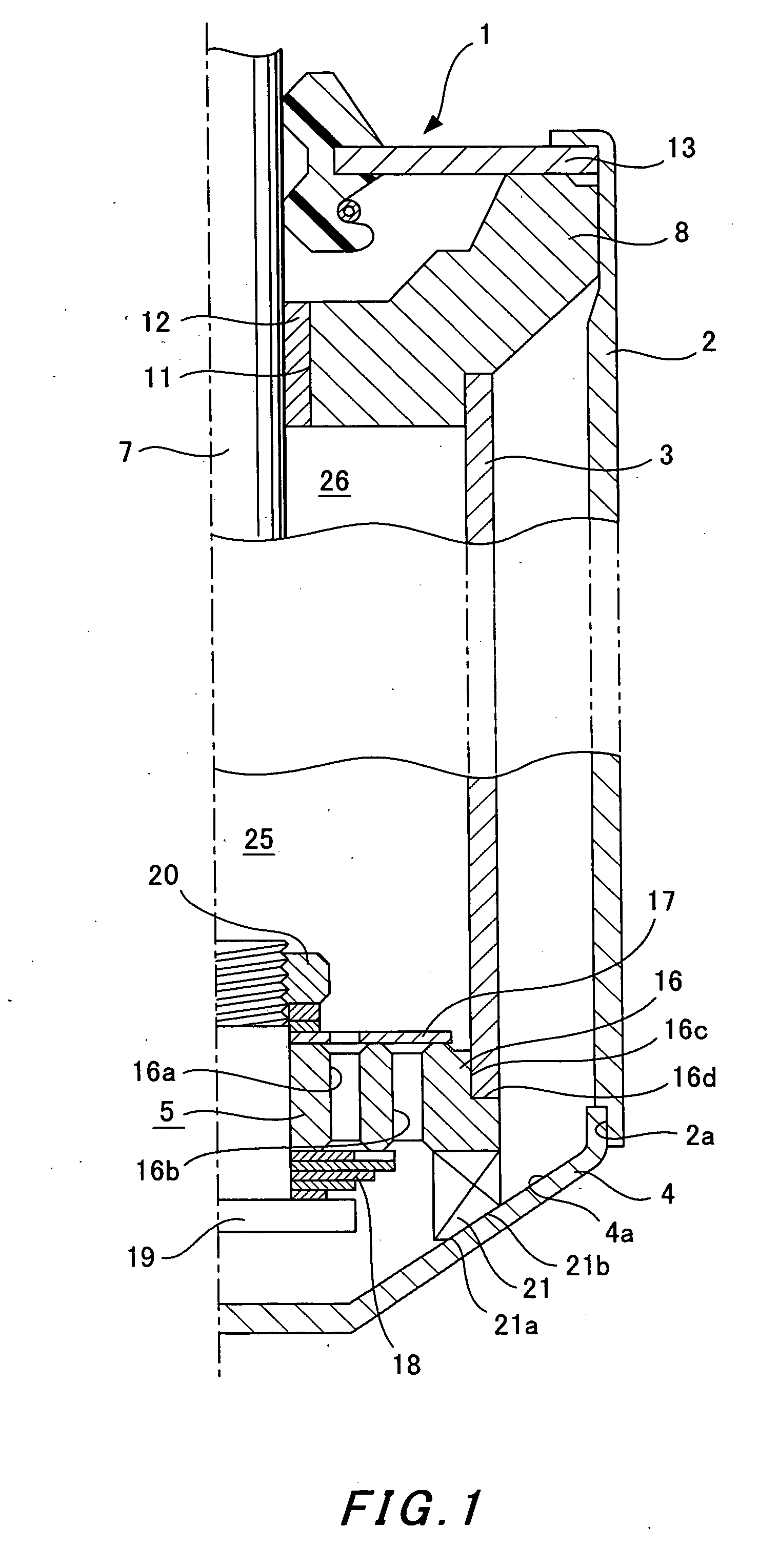
[0016] A double tube hydraulic shock absorber according to an embodiment of this invention will now be described. As shown in FIG. 1, a double tube hydraulic shock absorber 1 comprises an outer tube 2, an inner tube 3, a lower cap 4, a base valve 5, a piston rod 7, and a rod guide 8. The outer tube 2 and inner tube 3 are disposed concentrically. The lower cap 4 is attached to a base end of the outer tube 2. The base valve 5 is fitted and fixed to a base end of the inner tube 3, and fixed into position on an upper surface of the lower cap 4. The piston rod 7 is inserted into the inner tube 3 so as to be free to protrude and retract. The rod guide 8 seals a top side of the inner tube 3 and outer tube 2, and supports the piston rod 7 slidably.

[0017] The rod guide 8 is fitted so as to extend from an inner periphery on the top side of the outer tube 2 to an inner periphery on the top side of the inner tube 3. A guiding hole 11 for guiding the piston rod 7 is provided in the center of th...


PUM


Abstract

A double tube hydraulic shock absorber comprises: an outer tube; an inner tube; a base valve which is fitted and fixed to a base end of the inner tube; a lower cap provided so as to contact a leg portion of the base valve and seal a base end of the outer tube in an oil tight fashion; a piston rod inserted into the inner tube so as to be capable of an axial reciprocation; and a guide member attached to a top side of the outer tube and the inner tube so as to support the piston rod and apply an axial force on the inner tube. In this double tube hydraulic shock absorber, the leg portion of the base valve and the lower cap contact each other on a line of action of the axial force that is applied toward the base end of the inner tube.

Description

FIELD OF THE INVENTION [0001] This invention relates to a double tube hydraulic shock absorber used in a suspension device of an automobile, an industrial vehicle, or similar, and more particularly to an attachment structure for a base valve which is fixed into position on a lower cap when attached to a base end of an inner tube. BACKGROUND OF THE INVENTION [0002] JP11-201211A, published by the Japan Patent Office in 1999, discloses an attachment structure for a base valve which is fixed into position on a lower cap of a double tube hydraulic shock absorber. As shown in FIG. 3, a lower cap 34 is fitted into a base end of an outer tube 32 and welded thereto at its outer periphery such that the base end of the outer tube 32 is blocked in an oil tight fashion. A base valve 35, which is fitted and fixed to a base end of an inner tube 33, is fixed into position on an upper surface of the lower cap 34. [0003] The base valve 35 comprises a valve case 36, a non-return valve 37, a pressure s...

Claims


Application Information

Patent Timeline
IPC IPC(8): F16F9/00
CPCF16F9/062F16F9/364F16F9/3257F16F9/3235
Inventor MURAKAMI, TOMOHARU
Owner KYB CORP
Why Eureka
Try Eureka