Fluid controller

a technology of fluid controller and flow rate coefficient, which is applied in the direction of diaphragm valves, engine diaphragms, functional valve types, etc., can solve the problems of difficult to increase difficult to make the flow rate large, so as to increase the flow rate coefficient, reduce the size of the fluid controller, and increase the cross sectional area of the passage.

Active Publication Date: 2006-09-28
FUJIKIN INC
View PDF8 Cites 7 Cited by
  • Summary
  • Abstract
  • Description
  • Claims
  • Application Information

AI Technical Summary

Benefits of technology

[0019] In accordance with the fluid controller of the present invention, since it is possible to make the cross sectional area of the passage larger in comparison with the conventional structure, it is possible to increase a flow rate coefficient while keeping a size of the fluid controller fixed, or it is possible to achieve a downsizing of the fluid controller while keeping the flow rate coefficient.

Problems solved by technology

However, in the existing device, there are many cases that the fluid controller can not be increased in size due to a problem of an installation space, and it is hard to make the flow rate large.

Method used


Image

  • Fluid controller
  • Fluid controller
  • Fluid controller

Examples


Embodiment Construction

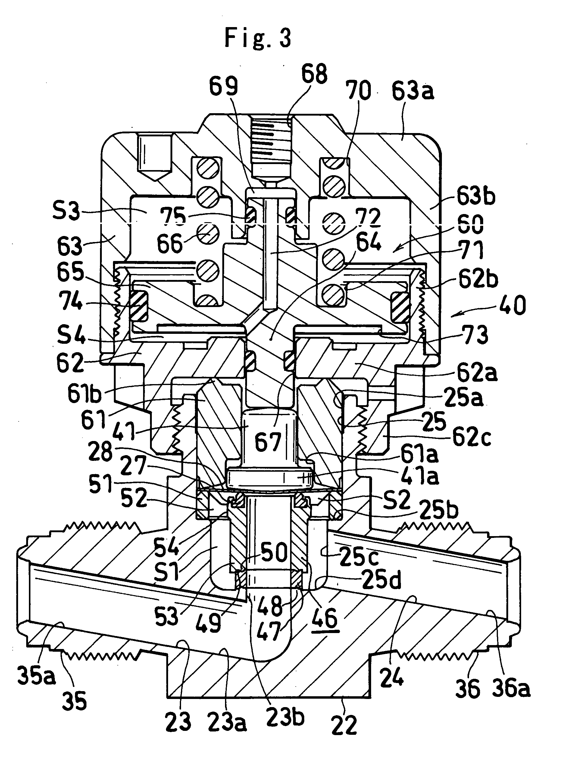
[0024] Description will be given below of embodiments in accordance with the present invention with reference to the accompanying drawings. In the following description, right and left mean right and left in the drawings.

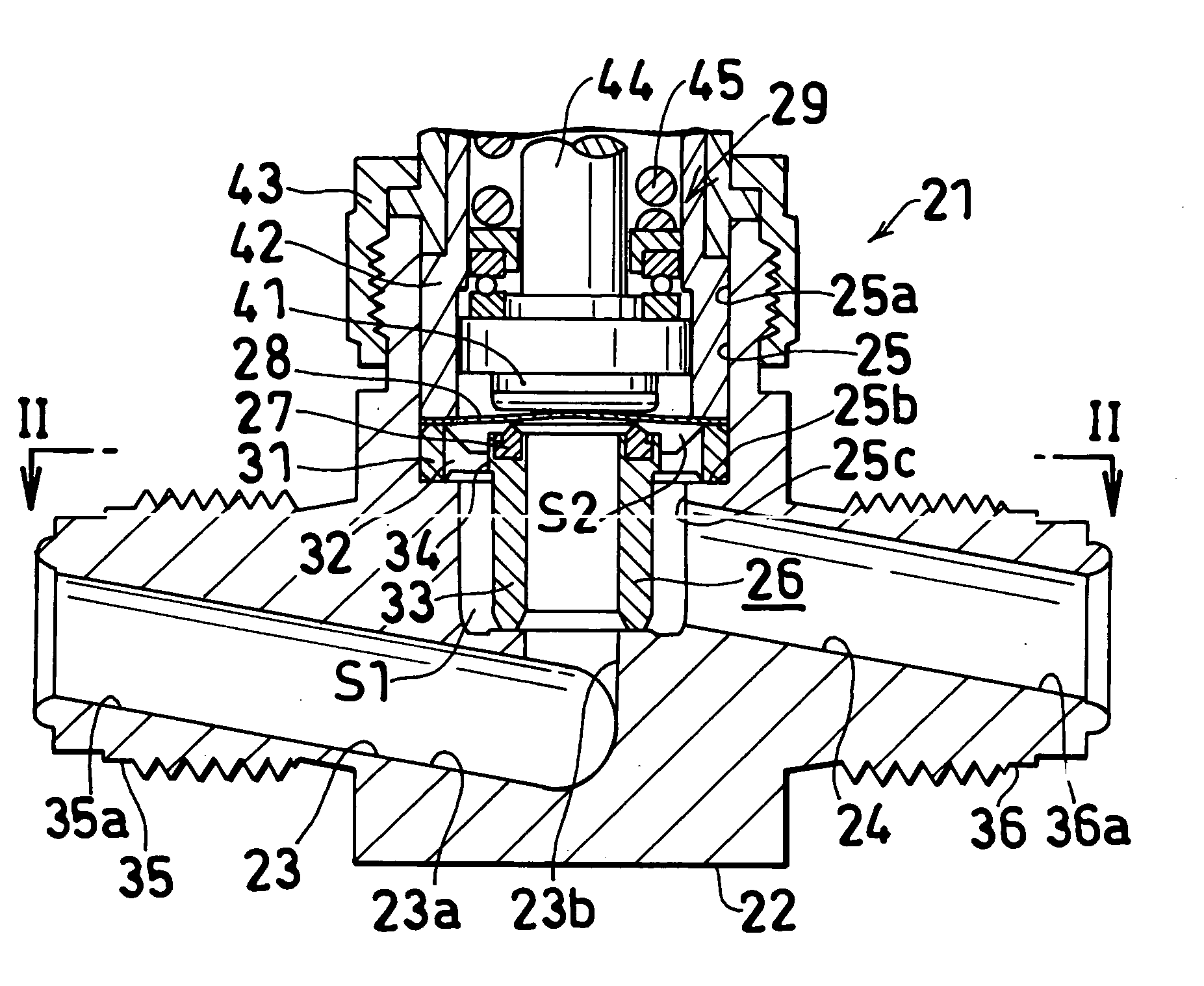
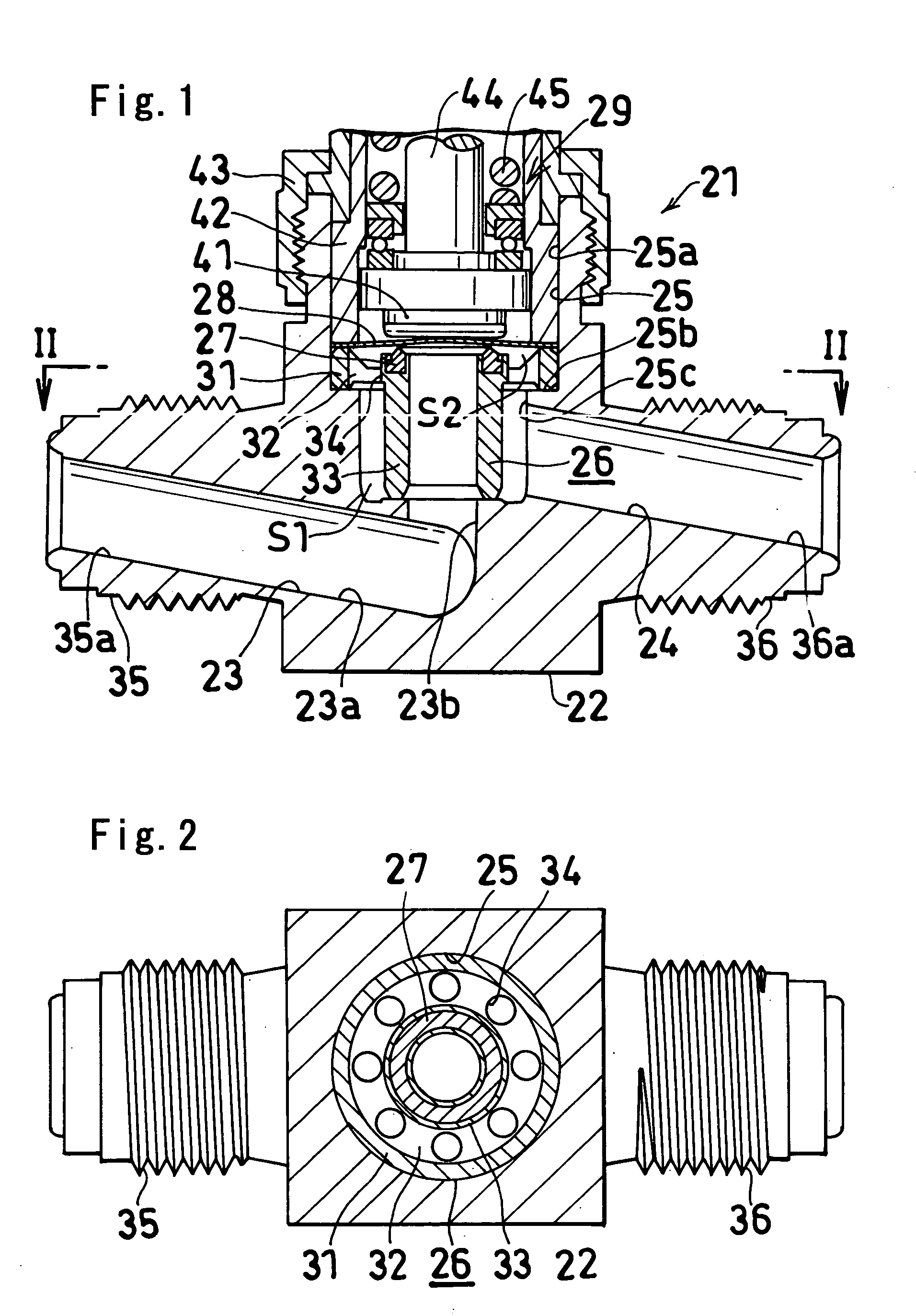
[0025]FIGS. 1 and 2 show one embodiment of a fluid controller in accordance with the present invention.

[0026] A fluid controller 21 comprises a block-like main body 22 having a fluid inflow passage 23, a fluid outflow passage 23 and a concave portion 25 open upward, a flow path forming disk 26 fitted to the concave portion 25 of the main body 22, an annular valve seat 27 arranged in the flow path forming disk 26, a diaphragm 28 pressed against or moved apart from the valve seat 27 so as to open and close the fluid passage 23, and an operation driving portion pressing the diaphragm 28 against the valve seat 27 or moving the diaphragm 28 apart from the valve seat 27.

[0027] The concave portion 25 includes a large-diameter portion 25a close to the opening and a small...


PUM


Abstract

A fluid controller, wherein the recessed port (25) of a body (22) is formed of larger diameter part (25a) near an opening and a small diameter part (25c) continued to the lower part of the large diameter part (25a) through a step part (25b). A flow passage forming disk (26) is fitted to the recessed portion (25). The fluid passage forming disk (26) comprises a large diameter cylindrical part (31) fitted to the large diameter part (25a) in the recessed portion, a connection part (32) supported by the step part (25b) in the recessed portion, and a small diameter cylindrical part (33) having an outer diameter smaller than the inner diameter of the small diameter part (25c) in the recessed portion and having a lower end supported by the bottom surface of the recessed portion (25). A plurality of through-holes (34) communicating an annular space (S1) on the outside of the small diameter cylindrical part with an annular space (S2) on the inside of the large diameter cylindrical part are formed at the connection part (32) of the flow passage forming disk. The fluid inflow passage (23) is led into the lower end of the small diameter cylindrical part (33) of the flow passage forming disk (26), and a fluid outflow passage (24) is led into the annular space (S1) on the outside of the small diameter cylindrical part.

Description

TECHNICAL FIELD [0001] The present invention relates to a fluid controller, in particular, a fluid controller suitable for treating a large flow rate of fluid. BACKGROUND ART [0002] A fluid controller to which the present invention is directed is called as a diaphragm valve and is used frequently (for example, refer to Patent Document 1=Japanese Unexamined Patent Publication No. 2003-42314). A typical structure thereof is shown in FIG. 4. [0003] A fluid controller 1 comprises a block-like main body 2 having a fluid inflow passage 2a, a fluid outflow passage 2b and a concave portion 2c open upward, an annular valve seat 3 arranged in a peripheral edge of the fluid inflow passage 2a, a diaphragm 4 pressed against or moved apart from the annular valve seat 3 so as to open and close the fluid passage 2a, a valve body presser foot 5 pressing the diaphragm 4 and capable of moving in a vertical direction, a cylindrical hood 6 having a lower end portion inserted to the concave portion 2c of...

Claims


Application Information

Patent Timeline
Patent Type & Authority Applications(United States)
IPC IPC(8): F16K1/00F16K15/00F16K7/14F16K7/16F16K7/17
CPCF16K7/14F16K7/16F16K7/12
Inventor TANIKAWA, TSUYOSHIITOI, SHIGERUYAKUSHIJIN, TADAYUKI
Owner FUJIKIN INC
Why Eureka
Try Eureka