Backlight apparatus and liquid crystal display apparatus

a technology of liquid crystal display and backlight unit, which is applied in the direction of lighting and heating apparatus, static indicating devices, instruments, etc., can solve the problem of large weight and achieve the effect of reducing manufacturing costs, weight saving, and simplifying backlight unit wiring

Inactive Publication Date: 2006-09-28
SONY CORP
View PDF4 Cites 30 Cited by
  • Summary
  • Abstract
  • Description
  • Claims
  • Application Information

AI Technical Summary

Benefits of technology

[0016] In the present invention, it is possible to simplify the wiring of the backlight unit using a bonding technique. Further, since unpackaged LED chips are used, manufacturing cost can be reduced.
[0017] Further, in the present invention, unpackaged LED chips are used for the backlight unit, that is, the LED chips are directly mounted. Therefore, it is possible to realize weight saving by the weight corresponding to the LED packages, as compared to the case of the conventional backlight unit. This can also contribute to a reduction in the thickness of the backlight unit.

Problems solved by technology

When the size of the backlight apparatus is increased, it is necessary to provide thousands of LEDs, resulting in a fairy large weight.

Method used


Image

  • Backlight apparatus and liquid crystal display apparatus
  • Backlight apparatus and liquid crystal display apparatus
  • Backlight apparatus and liquid crystal display apparatus

Examples


Embodiment Construction

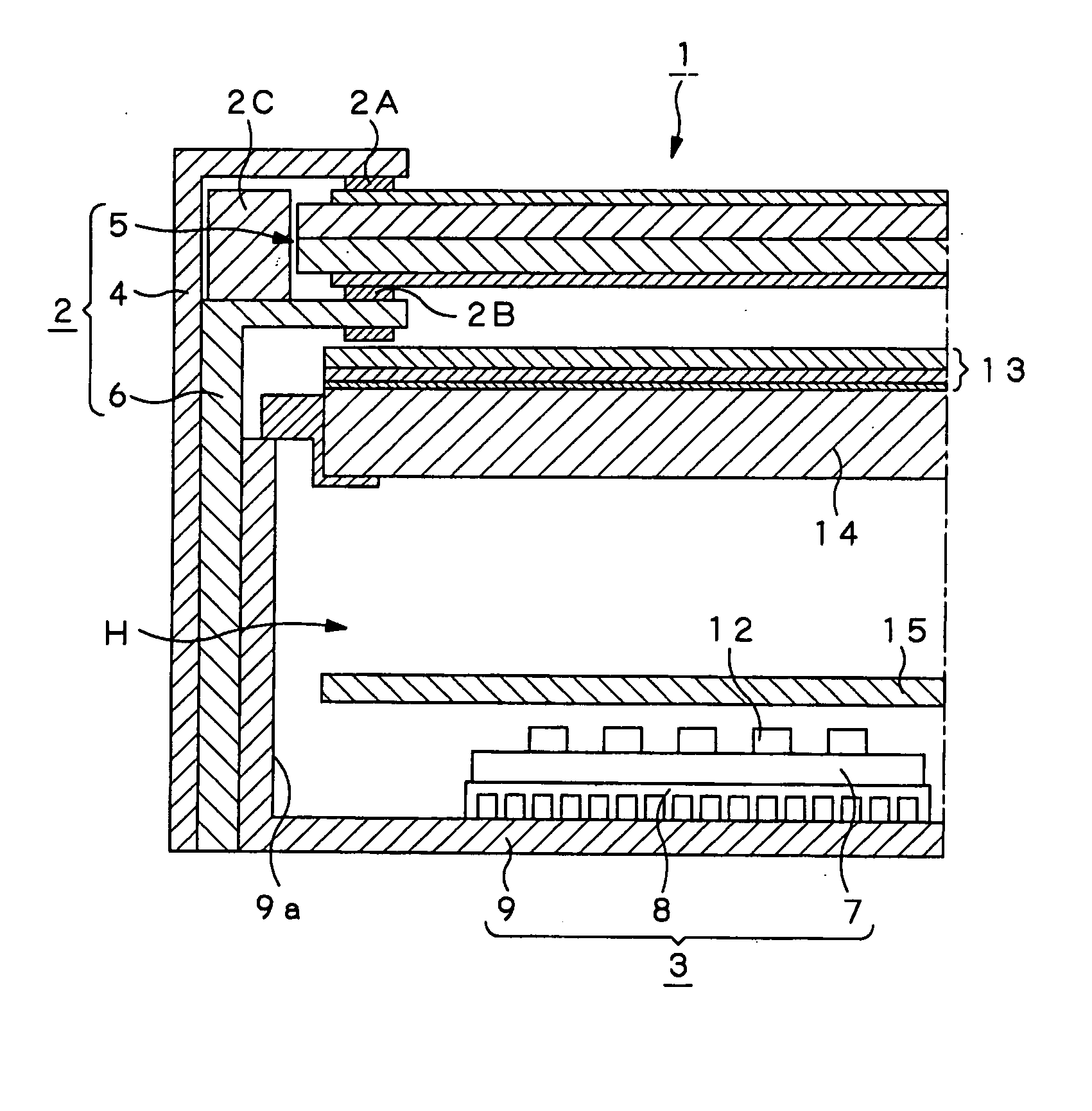
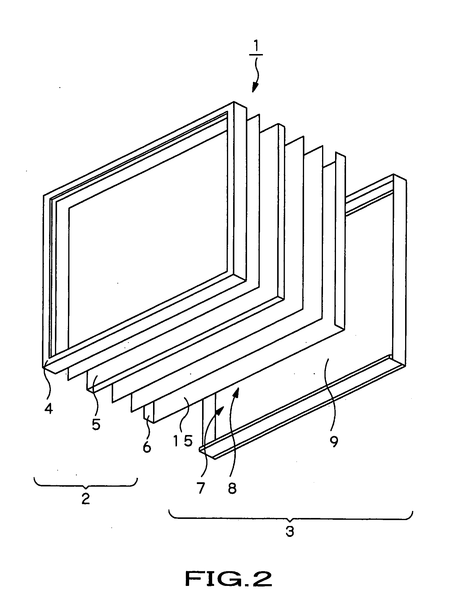
[0023] A transmissive liquid crystal display panel 1 shown in the accompanying drawings will be described in detail below as an embodiment of the present invention. The transmissive liquid crystal display panel 1 is used, for example, as a display panel of a television set with a large screen 40 inches or larger. As shown in FIGS. 2 and 4, the transmissive liquid crystal display panel 1 includes a liquid crystal panel unit 2 and a backlight unit 3 mounted on the back surface side of the liquid crystal panel unit 2 and supplies a display light thereto. The liquid crystal panel unit 2 includes a front frame member 4, a liquid crystal panel 5, and a back frame member 6 that holds the periphery of the liquid crystal panel 5 by sandwiching the same with the front frame member 4 through spacers 2A, 2B, and a guide member 2C.

[0024] Although the detail is omitted here, the liquid crystal panel 5 encapsulates a liquid crystal between first and second glass substrates whose opposed interval ...


PUM

PropertyMeasurementUnit
wavelength temperatureaaaaaaaaaa
reflectance ratioaaaaaaaaaa
currentaaaaaaaaaa

Abstract

The present invention has been made to reduce manufacturing cost of a liquid crystal display apparatus. The present invention provides a backlight apparatus including an LED chip substrate on which a plurality of red-LED (Light Emitting Diode) chips that emit red light, green-LED chips that emit green light, and blue-LED chips that emit blue light are arranged in a given manner, a diffusion section that is provided above the LED chip substrate and diffuses respective color lights emitted from the LED chips, a light amount detection section that detects the amount of the light emitted from the LED chip substrate, and an adjustment section that adjusts the amount of the current to be supplied to the LED chip substrate based on the light amount detected by the light amount detection section.

Description

CROSS REFERENCE TO RELATED APPLICATIONS [0001] The present invention contains subject matter related to Japanese Patent Application JP 2005-089492 filed in Japanese Patent Office on Mar. 25, 2005, the entire contents of which being incorporated herein by reference. BACKGROUND OF THE INVENTION [0002] 1. Field of the Invention [0003] The present invention relates to a backlight apparatus that illuminates a liquid crystal display section from the back thereof and a liquid crystal display apparatus including the backlight apparatus. [0004] 2. Description of the Related Art [0005] A liquid crystal display has some advantages, as compared to a CRT (Cathode-Ray Tube) screen. For example, an increase in the display size, and a reduction in the weight, thickness, and power consumption can be easily improved. Therefore, the liquid crystal display has increasingly been used for a television set and various types of displays together with, for example, a self-luminous PDP (Plasma Display Panel)...

Claims


Application Information

Patent Timeline
Patent Type & Authority Applications(United States)
IPC IPC(8): H01L29/00F21S2/00F21V29/00F21Y101/02G02F1/133G02F1/13357H01L33/00H05B37/02
CPCG09G3/3413G09G2360/145A61H39/086A61H2201/1688A61H2201/1685
Inventor SHIRAKUMA, TOSHIAKIOKITA, MASAMI
Owner SONY CORP
Why Eureka
Try Eureka