Plasma tube array and gas discharge tube

a technology of plasma tube array and gas discharge tube, which is applied in the direction of discharge tube luminescnet screen, gas exhaustion means, electrodes, etc., can solve the problems of significant increase in cost, difficult to dispose of protective layer and fluorescent material layer inside glass tube, etc., and achieves the effect of reducing the size of one pixel and achieving highly precise image display

Inactive Publication Date: 2006-09-28
SHINODA PLASMA
View PDF2 Cites 8 Cited by
  • Summary
  • Abstract
  • Description
  • Claims
  • Application Information

AI Technical Summary

Benefits of technology

[0023] The present invention has been made in view of the above circumstances and provides a plasma tube array, and a gas discharge tube suitable to be used for the plasma tube array, which can reduce the size of one pixel without making light emitting threads smaller in diameter and can realize a highly precise image display.
[0031] The plasma tube array of the present invention is provided with the light emitting tubes including plural types of fluorescent materials which are disposed in sequence therein and emit the fluorescent lights of different colors in the longitudinal direction, and the display electrodes are provided along the respective fluorescent materials disposed in sequence in the longitudinal direction of the light emitting tubes. Therefore, without reducing the diameter of the light emitting tube, the size of one pixel is made small, and a highly precise image can be displayed.
[0041] According to the present invention, without making the diameter of the light emitting thread (light emitting tube) small, the size of one pixel is reduced and a highly precise image display can be realized.

Problems solved by technology

Further, even if the glass tube of a small diameter can be prepared, the smaller in diameter the glass tube is made, the more it is difficult to dispose a protective layer and a fluorescent material layer inside the glass tube.
Hence, to realize the light emitting thread made significantly smaller in diameter than a diameter of 1 mm, a significant increase of the cost is anticipated.
However, according to the technique of this patent publication, since two pieces of rib-shaped partitions extending in the longitudinal direction for compartmentalizing three types of the fluorescent material layers in the boat are formed, there is a problem that the opening portions for emitting the fluorescent lights are narrowed by those partitions, thereby displaying a dark image.

Method used


Image

  • Plasma tube array and gas discharge tube
  • Plasma tube array and gas discharge tube
  • Plasma tube array and gas discharge tube

Examples


first embodiment

[0052]FIG. 4 is a view showing the array structure of the fluorescent material layers on the boat, which is the fluorescent support member in the plasma tube array of the present invention.

[0053] Here, on the boat 13, there is a fluorescent layer 14 composed of sequentially lined up three types of the fluorescent material layers 14R, 14G, 14B, 14R, 14G, 14B . . . that emit each of the florescent lights of three colors of R, G, and B in the longitudinal direction of the boat 13. These fluorescent material layers 14R, 14G, 14B, 14R, 14G, 14B . . . are formed in such a manner that an opened mask is arranged only on a portion where the fluorescent material intended to be coated so as to perform a screen printing, whereby the coated fluorescent material layers 14R, 14G, 14B, . . . are formed on the boat 13 as shown in FIG. 4.

[0054]FIG. 5 is a view showing the light emitting threads of the first embodiment.

[0055] The light emitting thread 10 shown here takes a glass tube 11 of 1 mm in d...

third embodiment

[0065] Next, the present invention will be described.

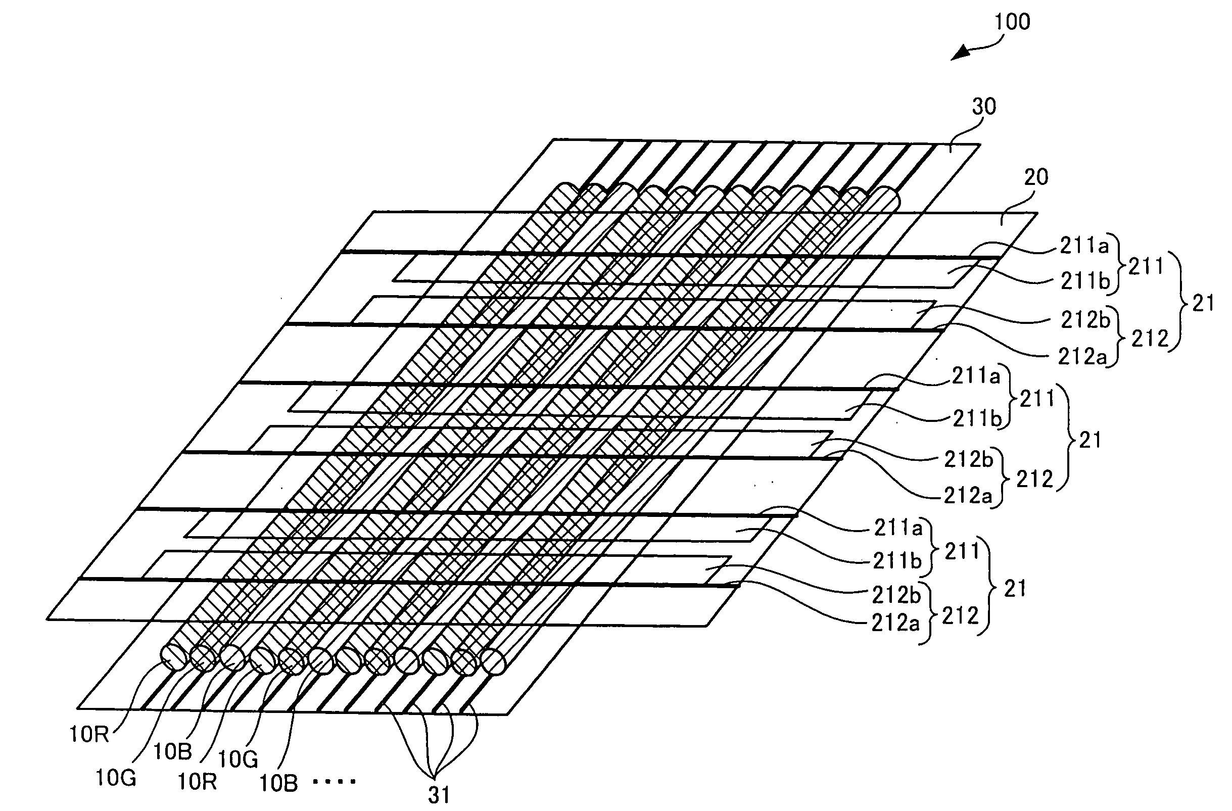
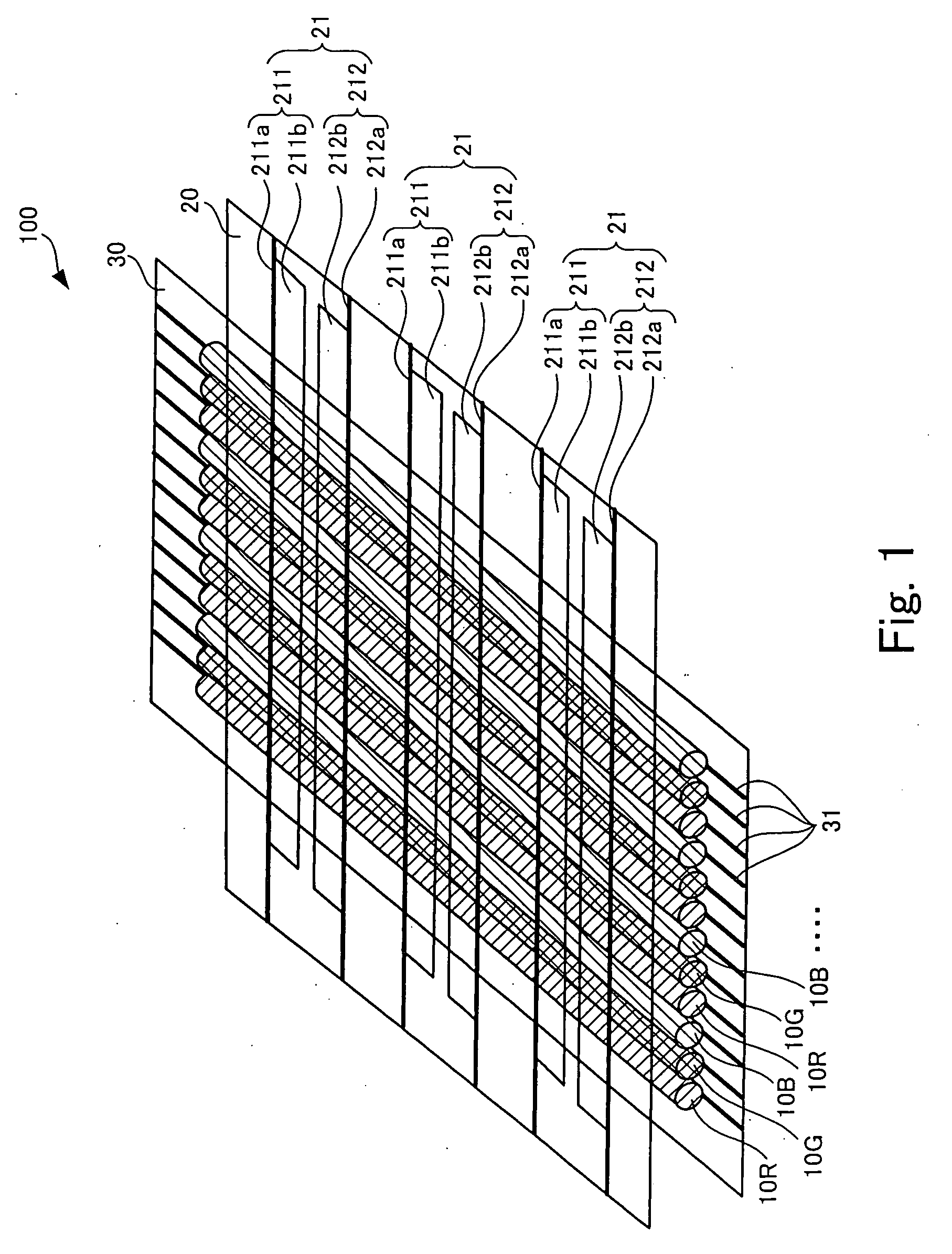
[0066]FIGS. 6 and 7 are an oblique view and a top view showing the array mode of light emitting threads of the third embodiment of the present invention.

[0067] Here, the different points with the first embodiment described by referring to FIGS. 4 and 5 will be described.

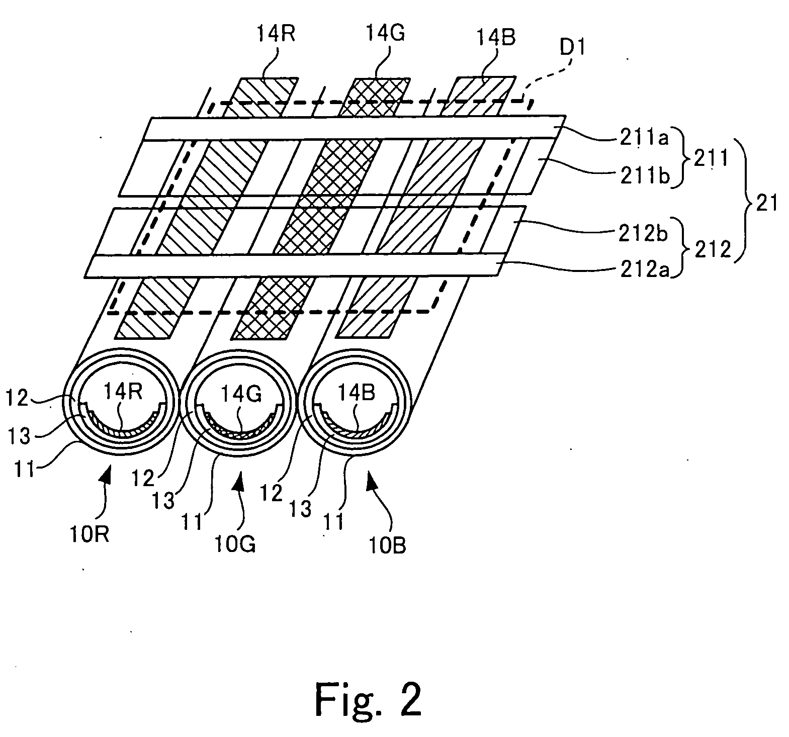
[0068] Fluorescent material layers 14R, 14G, 14B . . . provided in light emitting threads shown in FIGS. 6 and 7 are different in width in the alignment direction for each type, and as far as shown here, the width of the fluorescent material layer 14G that emits the fluorescent light of green (G) is the most widest, and a pair of display electrodes 21 also become a pair of display electrodes having the width according to the size of the fluorescent material layer. It should be noted that the pair of display electrodes 21, similarly to each of the preceding examples, have two pieces of display electrodes 211 and 212, and each of the display electrodes 211 and 212 ...

fourth embodiment

[0070] Next, the present invention will be described.

[0071]FIG. 8 is a view showing an array mode of light emitting threads in the fourth embodiment of the present invention. Here, the different points with the first embodiment described with reference to FIGS. 4 and 5 will be described.

[0072] In the present embodiment, light emitting threads 10 of the same structure and preparing method as the previously described first embodiment are used, and in FIG. 8, three pieces of light emitting threads adjacently lined up are shown. Each of the light emitting threads 10 has a boat 13 lined up in sequence with three types of the fluorescent material layers 14R, 14G, 14B . . . inserted into glass tubes 11 in the longitudinal direction.

[0073] However, in the present embodiment, on occasion of lining up the light emitting threads, as shown in FIG. 8, the position of the boat 13 is shifted by 0.03 mm by adjacent light emitting thread, whereby three types of the fluorescent material layers 14R,...


PUM


Abstract

A plasma tube array according to the present invention includes plural light emitting tubes that have fluorescent material layers inside and are mutually lined up in parallel. The plasma tube array includes pairs of display electrodes that are formed along the respective fluorescent material layers. The fluorescent material layers are disposed in sequence in the longitudinal direction of the light emitting tubes.

Description

BACKGROUND OF THE INVENTION [0001] 1. Field of the Invention [0002] The present invention relates to a plasma tube array and a gas discharge tube used for the plasma tube array, in which plural light emitting tubes each having fluorescent material layers inside are lined up, and electric discharge is generated within those plural light emitting tubes so as to allow the fluorescent material layers within the light emitting tubes to emit light, thereby displaying an image. [0003] 2. Description of the Related Art [0004] In general, as a large size image display apparatus performing an auto light generation, there has been disclosed a technique which makes use of a principle of plasma display to allow the light emitting thread made of tube (glass tube) of glass having fluorescent material layer and the like inside to line up in a large number and control light emission for each portion of each light emitting thread, thereby displaying an image (Japanese Patent Laid-Open No. 61-103187)....

Claims


Application Information

Patent Timeline
IPC IPC(8): H01J63/04H01J1/62H01J11/12H01J11/18H01J11/24H01J11/26H01J11/36H01J11/38H01J11/40H01J11/42H01J11/50H01J11/54H01J61/92H01J65/00
CPCH01J11/18
Inventor YAMAZAKI, YOSUKEISHIMOTO, MANABUYAMADA, HITOSHIHIRAKAWA, HITOSHITOKAI, AKIRASHINOHE, KOJIAWAMOTO, KENJI
Owner SHINODA PLASMA
Why Eureka
Try Eureka