Display control apparatus of display panel, and display device having display control apparatus

a display panel and control apparatus technology, applied in the direction of instruments, television systems, signal generators with optical-mechanical scanning, etc., can solve the problems of distorted display image during this period, user inability to tolerate displaying the whole black image in the frame, and the display control method is distorted, so as to avoid image distortion

Active Publication Date: 2006-09-28
MAXELL HLDG LTD
View PDF4 Cites 14 Cited by
  • Summary
  • Abstract
  • Description
  • Claims
  • Application Information

AI Technical Summary

Benefits of technology

[0016] An object of the present invention, therefore, is to provide a display control apparatus in which an image is prevented from being distorted when switching a video mode, and a display device having the display control apparatus.
[0018] A preferred embodiment in the abovementioned first aspect of the present invention, the display control apparatus has a video mode determination unit which determines a video mode on the basis of the input synchronizing signal, a display data generation unit which generates display data from the input video signal, a frame memory which stores the display data in correspondence to a frame, and a memory control unit which controls writing and reading of the display data with respect to the frame memory. The memory control unit writes first display data generated from an input video signal of a first frame into the frame memory, reads the first display data from the frame memory in a second frame which is subsequent to the first frame, and supplies this first display data to the display means. Further, when the video mode determination unit detects a change in a cycle of the input synchronizing signal in the second frame period, in respond to this the memory control unit repeatedly supplies the first display data to the display means during a subsequent predetermined number of frame periods. According to this configuration, when a change occurs in a cycle of the input synchronizing signal, during a subsequent period the first display data which is stored in the first frame prior to the occurrence of the change in the cycle is supplied to the display means, thus an image with no distortion can be displayed, and distortion of images can be avoided.
[0020] In a yet further preferred embodiment according to the abovementioned embodiments, the display data is repeatedly and continuously supplied until the video mode determination unit determines the stability of the cycle of the input synchronizing signal to determine the video mode. Accordingly, during a period of time in which the video mode is determined internally and internal operation is controlled under a new video mode, the same display data is outputted, and the display means can be caused to display a static image obtained from the display data. Therefore, at least distortion of images can be avoided.
[0022] According to the present invention, when the video mode is switched, an image with no distortion can be displayed, and distortion of images can be avoided.

Problems solved by technology

A problem in this case rises in the display control method when the video modes are switched.
Therefore, at the time of switching, display data of both channels are written in a frame memory in the frame in which the switching is generated, thus the same problem, which has occurred when switching the video mode, occurs.
Therefore, in several frame periods immediately after the video mode is switched, the video mode in the display control apparatus and the video mode of the input video signal do not conform to each other, thus the displayed image during this period is distorted.
However, displaying the whole black image in the frames is not always tolerated by users, thus other display control apparatus is desired.

Method used


Image

  • Display control apparatus of display panel, and display device having display control apparatus
  • Display control apparatus of display panel, and display device having display control apparatus
  • Display control apparatus of display panel, and display device having display control apparatus

Examples


Embodiment Construction

[0029] Embodiments of the present invention are described hereinafter with reference to the drawings. However, the technological scope of the present invention is not limited to these embodiments, thus the present invention extends to the technical scope described in the scope of the patent claims and to the equivalent items.

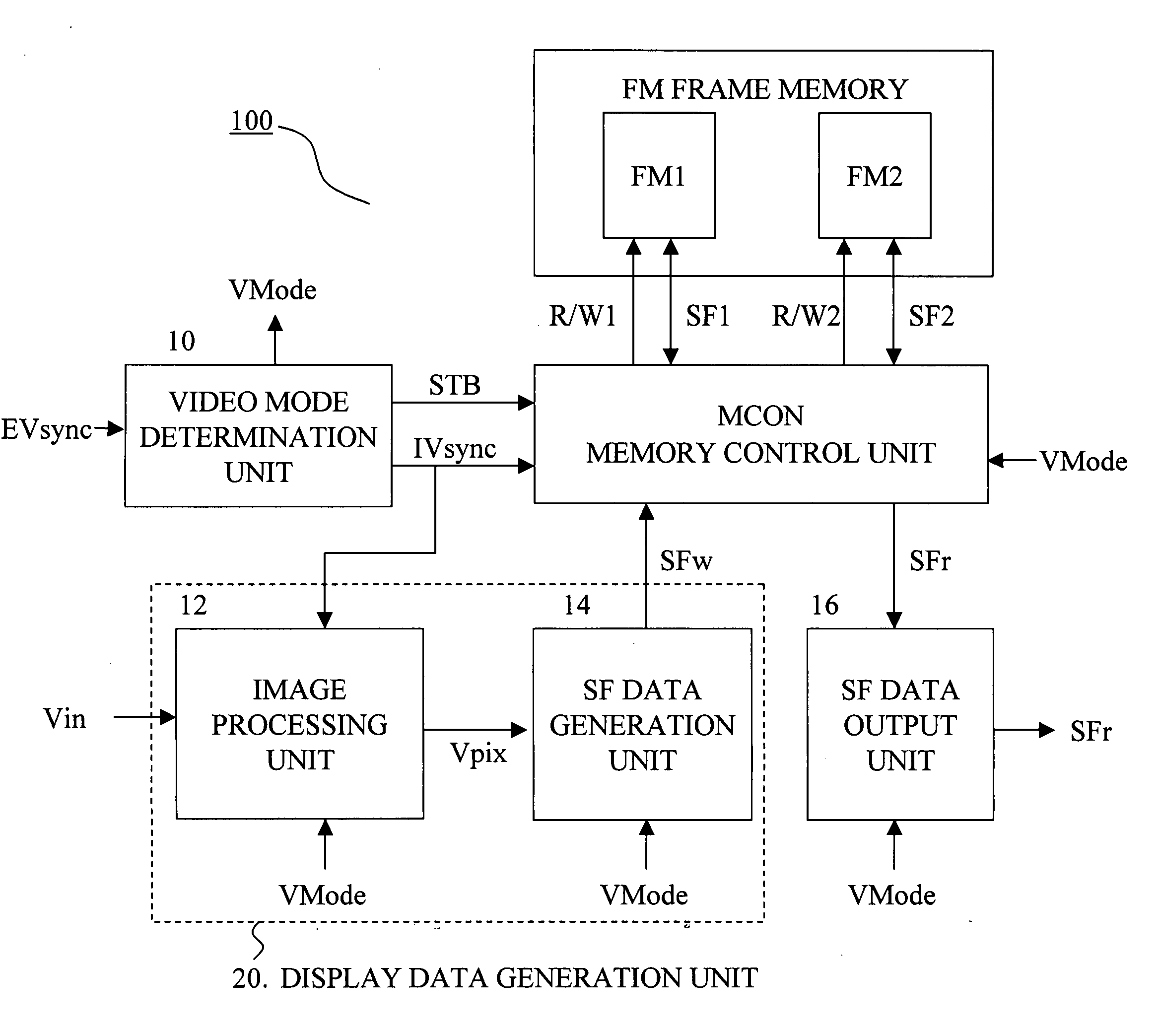
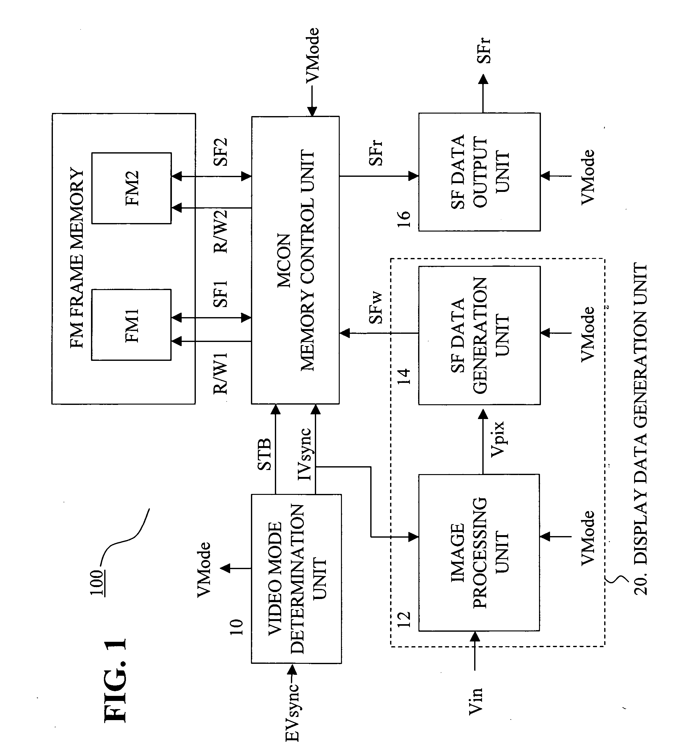
[0030]FIG. 1 is a configuration diagram of the display control apparatus according to an embodiment. A display control apparatus 100 of FIG. 1 comprises a video mode determination unit 10 which monitors a cycle of an external synchronizing signal EVsync to determine a video mode from the cycle, a display data generation unit 20 which generates display data SFw from an input video signal Vin, a frame memory FM in which the display data is stored temporarily, and a memory control unit MCON which controls writing and reading of the display data with respect to the frame memory FM. The video mode determination unit 10 monitors a cycle of the external synchronizing ...


PUM


Abstract

In a display control apparatus which is supplied with an input synchronizing signal and an input video signal, and which generates display data from the input video signal on the basis of the input synchronizing signal, and supplies the display data to display means, when a change is detected in a cycle of the input synchronizing signal, the display means is supplied with display data of a frame prior to the occurrence of the change in the cycle, throughout a subsequent predetermined number of frame periods.

Description

CROSS-REFERENCE TO RELATED APPLICATIONS [0001] This application is based upon and claims the benefit of priority from the prior Japanese Patent Application No. 2005-048488, filed on Feb. 24, 2005, the entire contents of which are incorporated herein by reference. BACKGROUND OF THE INVENTION [0002] 1. Field of the Invention [0003] The present invention relates to a display control apparatus of a display panel and a display device with the display control apparatus. Particularly the present invention relates to a display control apparatus which prevents distortion of a display screen when, for example, switching the video modes, and to a display device having the display control apparatus. [0004] 2. Description of the Related Art [0005] A display panel device to which the present invention is applied is a device such as a plasma display panel (“PDP” hereinafter) or a liquid crystal display panel (“LCD” hereinafter), which generates display data by performing predetermined signal proce...

Claims


Application Information

Patent Timeline
Patent Type & Authority Applications(United States)
IPC IPC(8): G09G5/00G09G3/20G09G3/36G09G5/18G09G5/397G09G5/399H04N5/46
CPCG09G3/2022G09G5/006G09G5/399G09G3/20H04N5/04H04N5/46
Inventor IKEDA, HIROKIUEDA, TOSHIO
Owner MAXELL HLDG LTD
Why Eureka
Try Eureka