Detection device

a detection device and detection technology, applied in the direction of distance measurement, instruments, and reradiation, to achieve the effect of adequate scan control and high precision

Inactive Publication Date: 2006-09-28
SANYO ELECTRIC CO LTD
View PDF6 Cites 12 Cited by
  • Summary
  • Abstract
  • Description
  • Claims
  • Application Information

AI Technical Summary

Benefits of technology

[0023] In the detection device according to the second aspect of the present invention, the scan trajectory can be corrected at the time of detection of the obstacle. Therefore, the movement of the obstacle and the state thereof can be detected with high precision.
[0024] That is, in the detection device according to the second aspect of the present invention, the scan frequency in the vicinity of the obstacle is increased, so the movement of the obstacle and the state thereof can be detected in great detail. Also, in the second aspect, when the scan trajectory of the laser beam is set so as to increase the scan frequency in the vicinity of the obstacle in the case where the distance to the obstacle is shorter then the threshold distance, it is possible to prevent unnecessary monitoring of an obstacle located in the far-off distance. Therefore, adequate scan control can be achieved.

Problems solved by technology

However, JP 11-325885 A does not describe how to control a laser beam scan state to be adapted to a high-speed driving mode, an obstacle detection mode, and a driving direction changing mode.

Method used


Image

  • Detection device
  • Detection device
  • Detection device

Examples


Embodiment Construction

[0042] Embodiments of the present invention will be described hereinafter with reference to the drawings. It should be noted that this embodiment is made by applying the present invention to a beam irradiation device loaded into a vehicle. In this embodiment, the presence or absence of an obstacle in a scanning region and distance to the obstacle are detected by radiating laser beams from a front portion of a vehicle and scanning the laser beams in the scanning region.

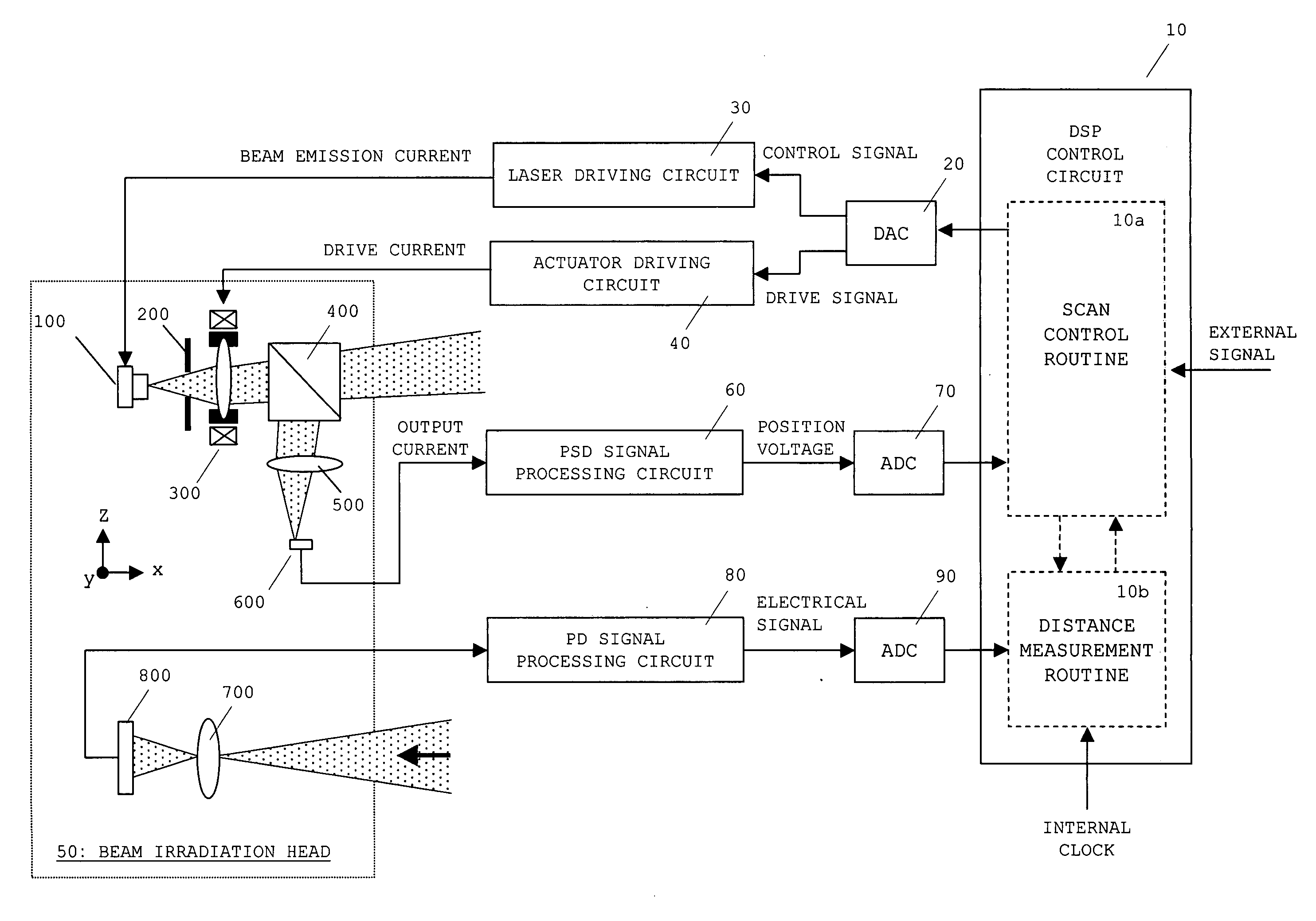
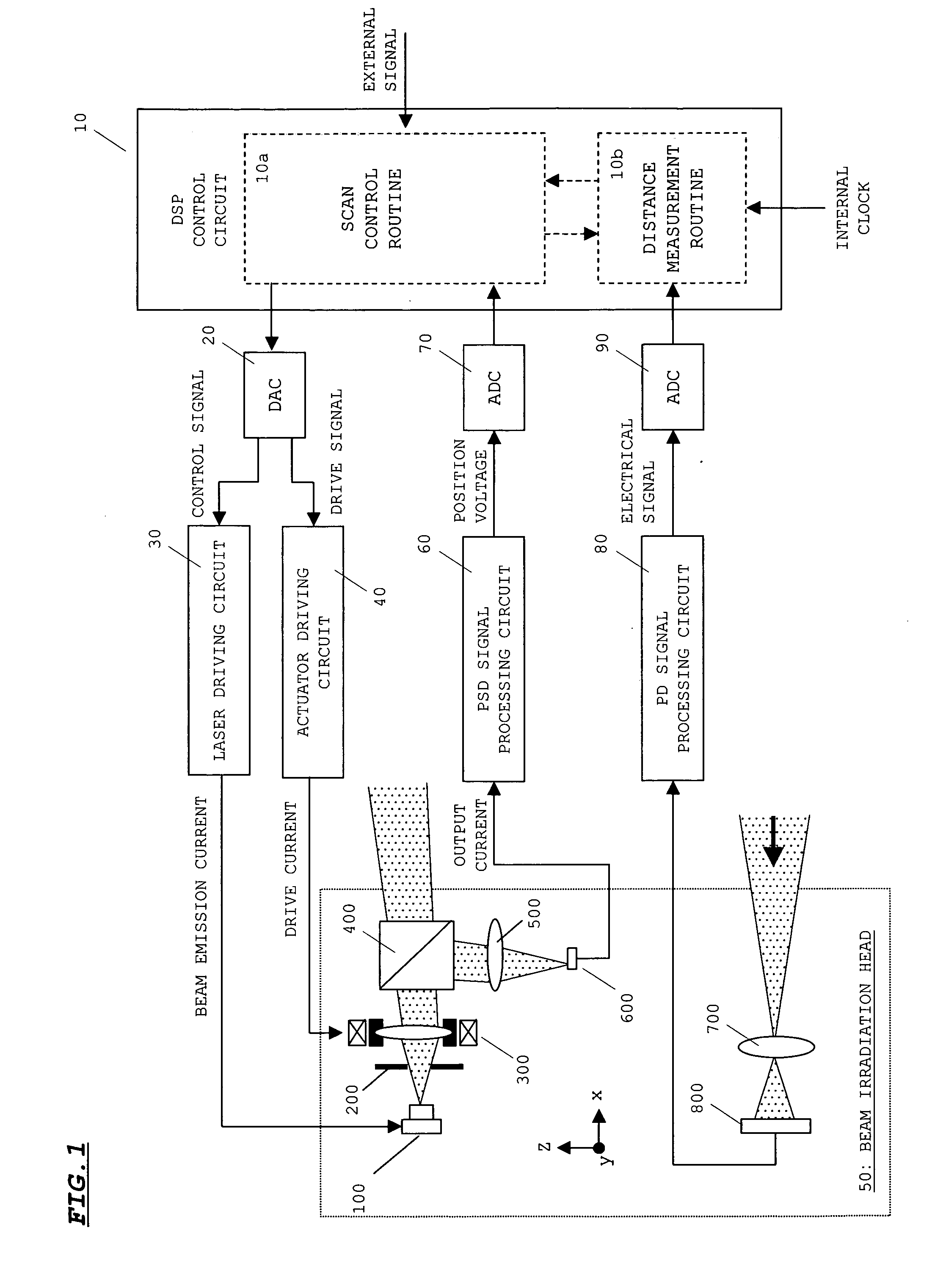
[0043]FIG. 1 shows the configuration of a beam irradiation device according to an embodiment of the present invention.

[0044] As shown in FIG. 1, a beam irradiation device is provided with a digital signal processor (DSP) control circuit 10, a digital analog converter (DAC) 20, a laser driving circuit 30, an actuator driving circuit 40, a beam irradiation head 50, a position sensitive detector (PSD) signal processing circuit 60, an analog digital converter (ADC) 70, a photo detector (PD) signal processing circuit 80 a...


PUM


Abstract

A scan trajectory of a laser beam is controlled based on external signals each related to a driving direction and a driving speed, a result obtained by detection of an obstacle, and signals related to distances to the obstacle. For example, at the time of a right turn, a scan trajectory for increasing scan frequency on a portion shifted in a right-turn direction from a center axis in a driving direction is set. At the time of high-speed driving, a scan trajectory for increasing scan frequency on a center portion in the driving direction is set. When the obstacle is detected at a position corresponding to a distance shorter than a threshold distance, a scan trajectory for increasing scan frequency in the vicinity of the obstacle is set. Detection of the obstacle and monitoring of a state thereof are adequately and smoothly performed at the time of changing of the driving direction, the time of high-speed driving, and the time of detection of the obstacle.

Description

BACKGROUND OF THE INVENTION [0001] 1. Field of the Invention [0002] The present invention relates to a detection device for detecting an obstacle within a target region by emitting a laser beam to the target region, which is suitable, for example, to be mounted on a moving object such as a vehicle or an airplane. [0003] 2. Description of the Related Art [0004] In recent years, in order to improve driving safety, a detection device for detecting an obstacle ahead in a driving direction of a vehicle or the like is mounted, for example, on a family vehicle. The detection device scans a target region with a laser beam to detect the presence or absence of the obstacle within the target region based on the presence or absence of a reflection beam of the laser beam. During normal driving, a scan pattern is set so as to scan with the laser beam the entire target region set ahead in the driving direction of the vehicle. A pulse beam is outputted to a predetermined position on the scan patter...

Claims


Application Information

Patent Timeline
Patent Type & Authority Applications(United States)
IPC IPC(8): G01C3/08G01P3/36G01S17/931
CPCG01C3/08G01S17/46G01S17/936G01S17/931
Inventor YAMAGUCHI, ATSUSHIKOBAYASHI, SHINJIYAMADA, MASATOICHIURA, SHUICHI
Owner SANYO ELECTRIC CO LTD
Why Eureka
Try Eureka