Lens driving mechanism, lens unit and image pickup apparatus

Active Publication Date: 2006-09-28
SONY CORP
View PDF4 Cites 11 Cited by
  • Summary
  • Abstract
  • Description
  • Claims
  • Application Information

AI Technical Summary

Benefits of technology

[0012] Therefore, with the lens driving mechanism, since a piezoelectric element is used as the driving section and the initial position of the movable block is set when the movable block is restricted by the restriction section, miniaturization of a lens driving mechanism can be achieved and the setting of the initial position can be set with ease.
[0013] Preferably, the movable range of the movable block is set based on the set initial position of the movable block. With the lens driving mechanism, facilitation in operation control of the movable block and enhancement of the reliability in operation of the movable block can be anticipated.
[0014] The detection section may include a strain gauge which detects an amount of distortion appearing with the piezoelectric element. The use of a strain gauge facilitates the detection without

Problems solved by technology

However, since, in such a conventional image pickup apparatus as described above, a linear actuator formed form a driving coil, a driving magnet and so forth is used for the lens driving mechanism, the image pickup apparatus has a problem in that it requires a complicated structure and

Method used


Image

  • Lens driving mechanism, lens unit and image pickup apparatus
  • Lens driving mechanism, lens unit and image pickup apparatus
  • Lens driving mechanism, lens unit and image pickup apparatus

Examples


Embodiment Construction

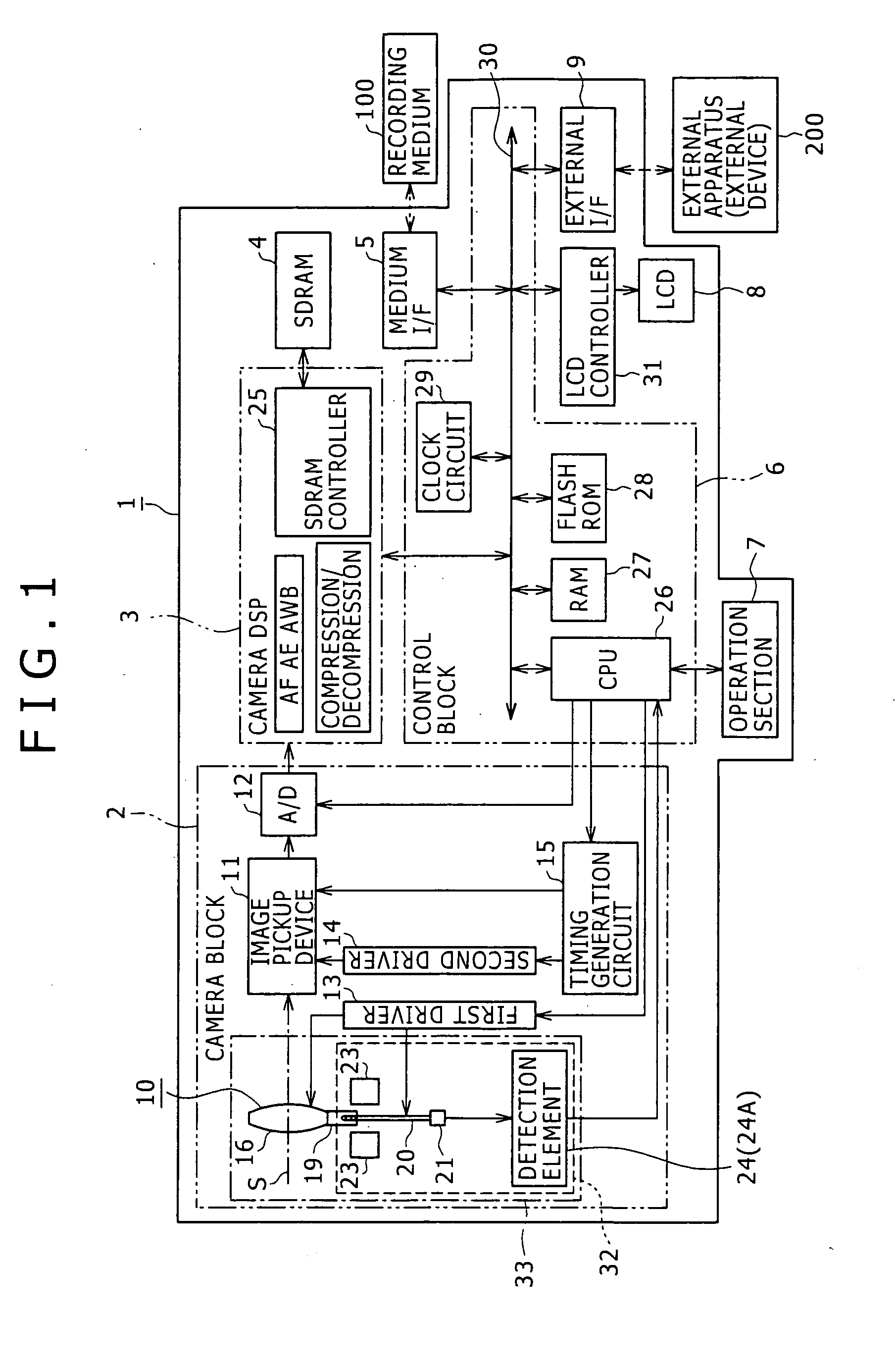
[0028] Although the present invention can be applied to various image pickup apparatus which have a moving picture image pickup function or a still picture image pickup function such as portable telephone sets, video cameras and still cameras and also to various lens units and lens driving mechanisms used in such image pickup apparatus, a general configuration of an image pickup apparatus to which the present invention is described first with reference to FIG. 1.

[0029] The image pickup apparatus 1 includes a camera block 2, a camera DSP (Digital Signal Processor) 3, an SDRAM (Synchronous Dynamic Random Access Memory) 4, a medium interface (I / F) S, a control block 6, an operation section 7, a LCD (Liquid Crystal Display) unit 8 and an external interface (I / F) 9. A recording medium 100 can be removably loaded into the external interface 9.

[0030] For the recording medium 100, various media can be used including memory cards in which a semiconductor memory is incorporated and disk-typ...


PUM


Abstract

A lens driving mechanism is disclosed which can achieve miniaturization of the mechanism by simplification and enhancement of the reliability in position control of a movable block. The lens driving mechanism includes a piezoelectric element deformed when energized for functioning as a driving section for applying driving force to the movable block, a restriction section for restricting the movement of the movable block in the predetermined direction, and a detection section for detecting a predetermined amount regarding the piezoelectric element. The initial position of the movable block is set as a position at an extremity of the movement of the movable block within a movable range based on an inflection point of the predetermined amount detected by the detection section when the movable block moved by the deformation of the piezoelectric element is restricted by the restriction section.

Description

CROSS REFERENCES TO RELATED APPLICATIONS [0001] The present invention contains subject matter related to Japanese Patent Application JP 2005-083640, filed in the Japanese Patent Office on Mar. 23, 2005, the entire contents of which being incorporated herein by reference. BACKGROUND OF THE INVENTION [0002] This invention relates to a lens driving mechanism, a lens unit and an image pickup apparatus. [0003] A lens unit wherein an image pickup optical system including a movable lens or the like and a lens driving mechanism for moving the movable lens in a predetermined direction are disposed in a lens barrel is incorporated not only in video cameras and still cameras but also in various image pickup apparatus of portable telephone sets and like devices. The movable lens cooperates with a lens holder which holds the movable lens thereon to form a movable block. The movable block is moved by the lens driving mechanism in a direction of an optical axis to perform focusing or zooming and a...

Claims


Application Information

Patent Timeline
IPC IPC(8): G02B7/02
CPCG02B7/023G02B7/102G02B7/08G03B3/12G03B3/02G03B2205/0061
Inventor MAKII, TATSUO
Owner SONY CORP
Why Eureka
Try Eureka