Rotation Drive Force Transmission Mechanism, Constant Velocity Universal Joint and Resin Joint Boot Constructing the Mechanism, and Method of Tightening Clamp Band for Constant Velocity Universal Joint

a transmission mechanism and constant velocity technology, applied in mechanical devices, manufacturing tools, couplings, etc., can solve the problems of reducing the sealing function of the joint boot, increasing surface pressure, and reducing the shock applied, so as to reduce the amount of shock applied, reduce the deformation stress acting on the bellows, and the effect of reducing the thickness

Inactive Publication Date: 2009-01-15
HONDA MOTOR CO LTD
View PDF8 Cites 9 Cited by
  • Summary
  • Abstract
  • Description
  • Claims
  • Application Information

AI Technical Summary

Benefits of technology

[0050]Therefore, by setting the wall thickness and rigidity of this peak, the length by which the synthetic resin boot is extended and contracted or curved can be controlled. Stated otherwise, the spring constant of the boot can easily be set within a given range. Consequently, the displacement of a driven shaft coupled to the constant-velocity joint can be controlled.
[0051]The space provided in the boot is effective in reducing shocks applied to the boot when foreign matter such as pebbles or the like hit the boot.
[0052]One of the valleys which is closest to the large-diameter tube should preferably have a radius of curvature greater than those of the remaining valleys. Since the valley which is closest to the large-diameter tube is more flexible than the other valleys, deforming stresses acting on the bellows are reduced when this valley is extended and contracted or curved. Consequently, the peak, which has the greatest wall thickness and which is less deformable, is not subject to stress concentrations, and the boot portion between this peak and the large-diameter tube is prevented from cracking.
[0053]By thus setting the radius of curvature of the valley, the distance by which the valley is extended and contracted or curved can be controlled. With the radius of curvature of the valley being thus set, in addition to the wall thickness of the peak that is closest to the large-diameter tube, the spring constant of the synthetic resin boot may be set with ease.
[0054]The large-diameter tube and the small-diameter tube of the boot of synthetic resin usually have band mounting slots in which boot bands are tightened. Preferably, the boot should have a curved portion extending from a bottom of the band mounting slot in the small-diameter tube to a side wall of one of the peaks which is closest to the small-diameter tube. The curved portion is effective to give a large wall thickness to a boot portion between the small-diameter tube and the bellows. Therefore, the boot portion between the small-diameter tube and the bellows is rigid enough to prevent the boot portion from cracking, even when subjected to stress concentrations.

Problems solved by technology

In this case, however, as the outside diameter of the outer member increases, the crimping force (surface pressure) applied per unit area of the inner circumferential wall surface of the fastening band decreases, resulting in a greater tendency for the large-diameter tube to be displaced, and hence reducing the sealing function of the joint boot.
Conversely, as the outside diameter of the outer member decreases, the surface pressure increases, and the fastening band is more liable to tighten the large-diameter tube excessively.
Therefore, the large-diameter tube is extended, tending to shorten the service life of the joint boot.
This approach, however, requires a tedious and time-consuming process of experimentally confirming an appropriate crimped quantity of the fastening band for each of various outside diameters of the outer member.
However, if the land is lowered in height in order to allow the large-diameter tube of the joint boot to be fitted easily over the end of the outer member, then the sealing capability is reduced.
In addition, when the fastening band is crimped, the land is not snugly fitted in the engaging groove, and therefore the large-diameter tube of the joint boot is apt to become displaced in directions into or out of the outer member, and hence is difficult to be positioned reliably with respect to the boot mount.

Method used


Image

  • Rotation Drive Force Transmission Mechanism, Constant Velocity Universal Joint and Resin Joint Boot Constructing the Mechanism, and Method of Tightening Clamp Band for Constant Velocity Universal Joint
  • Rotation Drive Force Transmission Mechanism, Constant Velocity Universal Joint and Resin Joint Boot Constructing the Mechanism, and Method of Tightening Clamp Band for Constant Velocity Universal Joint
  • Rotation Drive Force Transmission Mechanism, Constant Velocity Universal Joint and Resin Joint Boot Constructing the Mechanism, and Method of Tightening Clamp Band for Constant Velocity Universal Joint

Examples


Embodiment Construction

[0080]A rotation drive force transmission mechanism, a constant-velocity joint and a resin-made joint boot therefor, together with a method of crimping a fastening band according to embodiments of the present invention, shall be described below with reference to the accompanying drawings. The rotation drive force transmission mechanism is typically incorporated in a motor vehicle such as an automobile or the like.

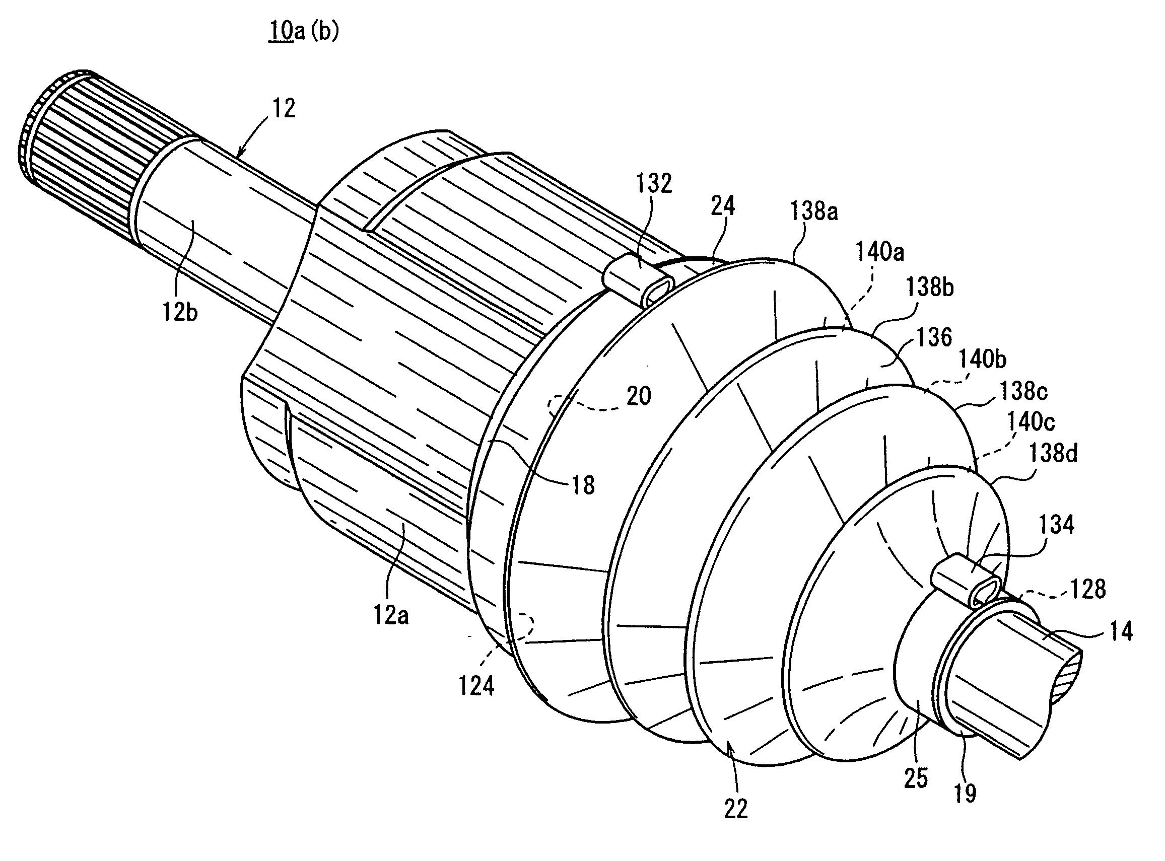
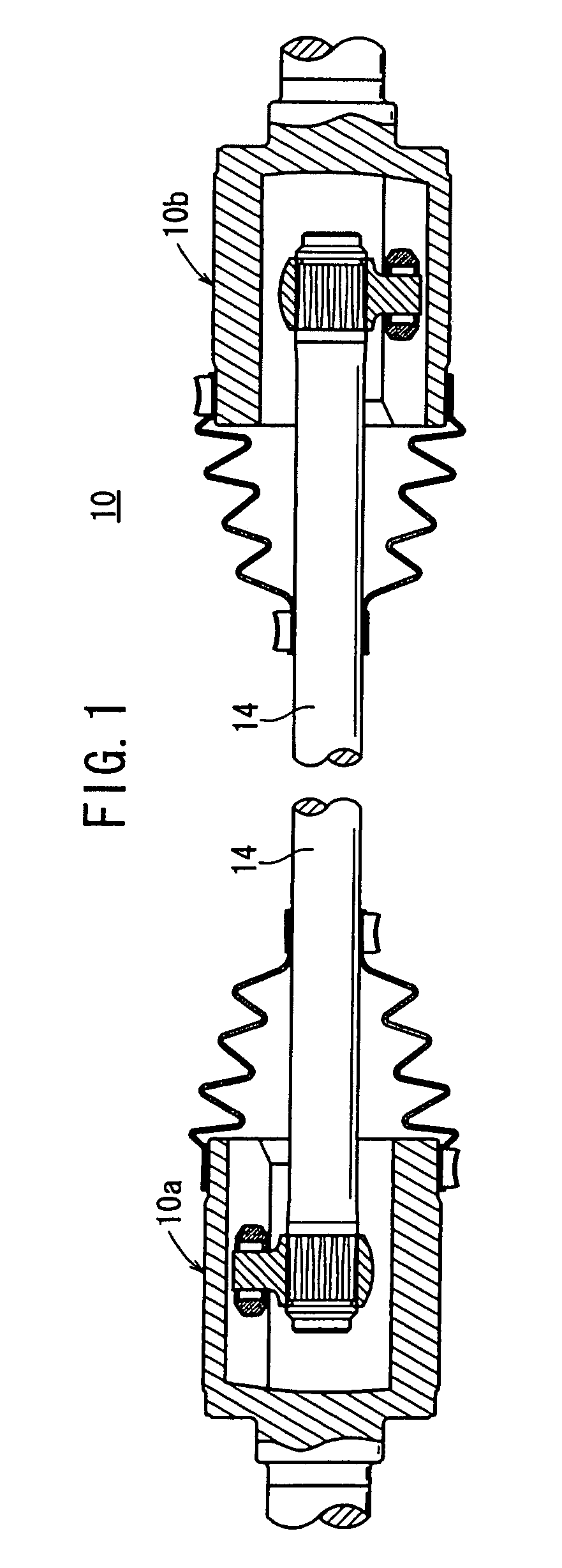
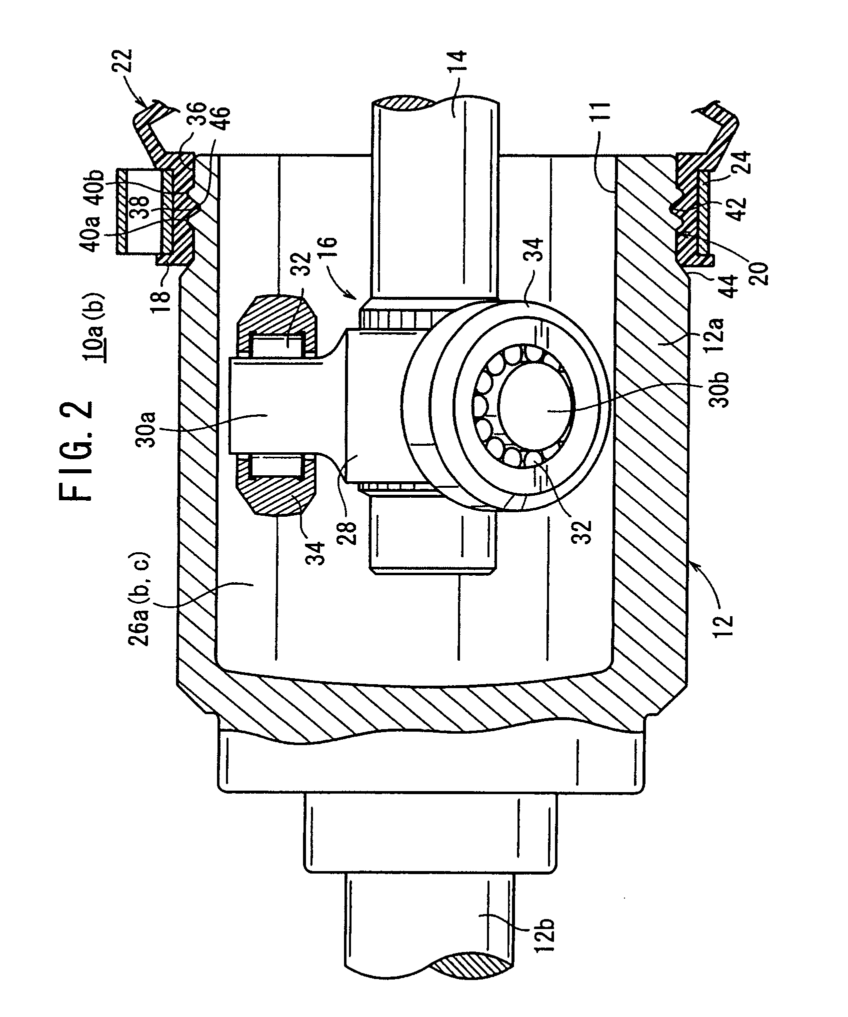
[0081]FIG. 1 is a longitudinal cross-sectional view, taken in an axial direction, of a rotation drive force transmission mechanism 10 according to an embodiment of the present invention. As shown in FIG. 1, the rotation drive force transmission mechanism 10 comprises a shaft 14, a first tripod constant-velocity joint 10a coupled to an end of the shaft 14 for axial sliding movement thereon, and a second tripod constant-velocity joint 10b coupled to the other end of the shaft 14 for axial sliding movement thereon. The first and second tripod constant-velocity joints 10a, 10b ...


PUM

PropertyMeasurementUnit
diameteraaaaaaaaaa
rotational drive forceaaaaaaaaaa
velocityaaaaaaaaaa

Abstract

A rotation drive force transmission mechanism has tripod constant-velocity joints coupled to respective ends of a shaft in opposite phase. Outer members of the tripod constant-velocity joints and portions of the shaft are covered with boots. When the large-diameter tube of each of the boots is fastened to the corresponding outer member by a first fastening band, a band crimping ratio is managed so as to fall within a predetermined range. Each of the outer members has a boot mount whose shape is selected to satisfy predetermined equations.

Description

TECHNICAL FIELD[0001]The present invention relates to a rotation drive force transmission mechanism, a constant-velocity (universal) joint and a resin-made joint boot therefor, and to a method of crimping or tightening a fastening (clamp) band to position and fix the fastening band on an outer member of a constant-velocity joint.BACKGROUND ART[0002]Motor vehicles such as automobiles or the like have a rotation drive force transmission mechanism for transmitting a rotational drive force produced by any of various prime movers such as an internal combustion engine, a motor, etc. to tires. The rotation drive force transmission mechanism generally employs a constant-velocity joint for transmitting the rotational drive force from one shaft to another shaft.[0003]In efforts to simplify and reduce the size and weight of a transmitting structure of a driven-shaft power transmitting system, the applicant of the present application has proposed a driven force transmitting structure having tri...

Claims


Application Information

Patent Timeline
Patent Type & Authority Applications(United States)
IPC IPC(8): F16D3/84B23P11/00
CPCF16D3/845Y10T29/49908F16J3/042F16D3/2055
Inventor OKUBO, SHIGERU
Owner HONDA MOTOR CO LTD
Why Eureka
Try Eureka