Timing synchronization module and method for synchronously playing a media signal

a technology of synchronizing module and media signal, which is applied in the direction of pulse transformer, selective content distribution, pulse technique, etc., can solve the problems of media signal inability to synchronize and play successfully, incomplete clock signal output of output module at the beginning, and incompleteness

Inactive Publication Date: 2006-09-28
QUISDA CORP
View PDF9 Cites 37 Cited by
  • Summary
  • Abstract
  • Description
  • Claims
  • Application Information

AI Technical Summary

Benefits of technology

[0009] The invention achieves the above-identified object by providing a timing synchronization module for control the playing of a media signal. The timing synchronization module includes a phase locked loop (PLL) and a synchronization processing unit. The PLL is for receiving an output-end clock signal. When the PLL receives the output-end clock signal for the first time, the PLL generates a reception-end clock signal according to the output-end clock signal. The synchronization processing unit is for receiving a procedure clock signal and the reception-end clock signal. The output-end clock signal has M clocks after the reception-end clock signal is generated, the reception-end clock signal has N clocks as generated, and when a difference value of M and N is larger than a preset value, the synchronization processing unit removes the media signal corresponding to the procedure clock signal and generates the reception-end clock signal again. When the difference value is smaller than the preset value, the PLL outputs the reception-end clock signal, and the synchronization processing unit controls the playing of the media signal according to the reception-end clock signal and the procedure clock signal.

Problems solved by technology

However, the clock signals outputted by the output module may be incomplete at the beginning, or become incomplete as received by the reception module due to network delay, interference, or other factors in transmission.
As a result, the media signals cannot be synchronized and played successfully.

Method used


Image

  • Timing synchronization module and method for synchronously playing a media signal
  • Timing synchronization module and method for synchronously playing a media signal
  • Timing synchronization module and method for synchronously playing a media signal

Examples


first embodiment

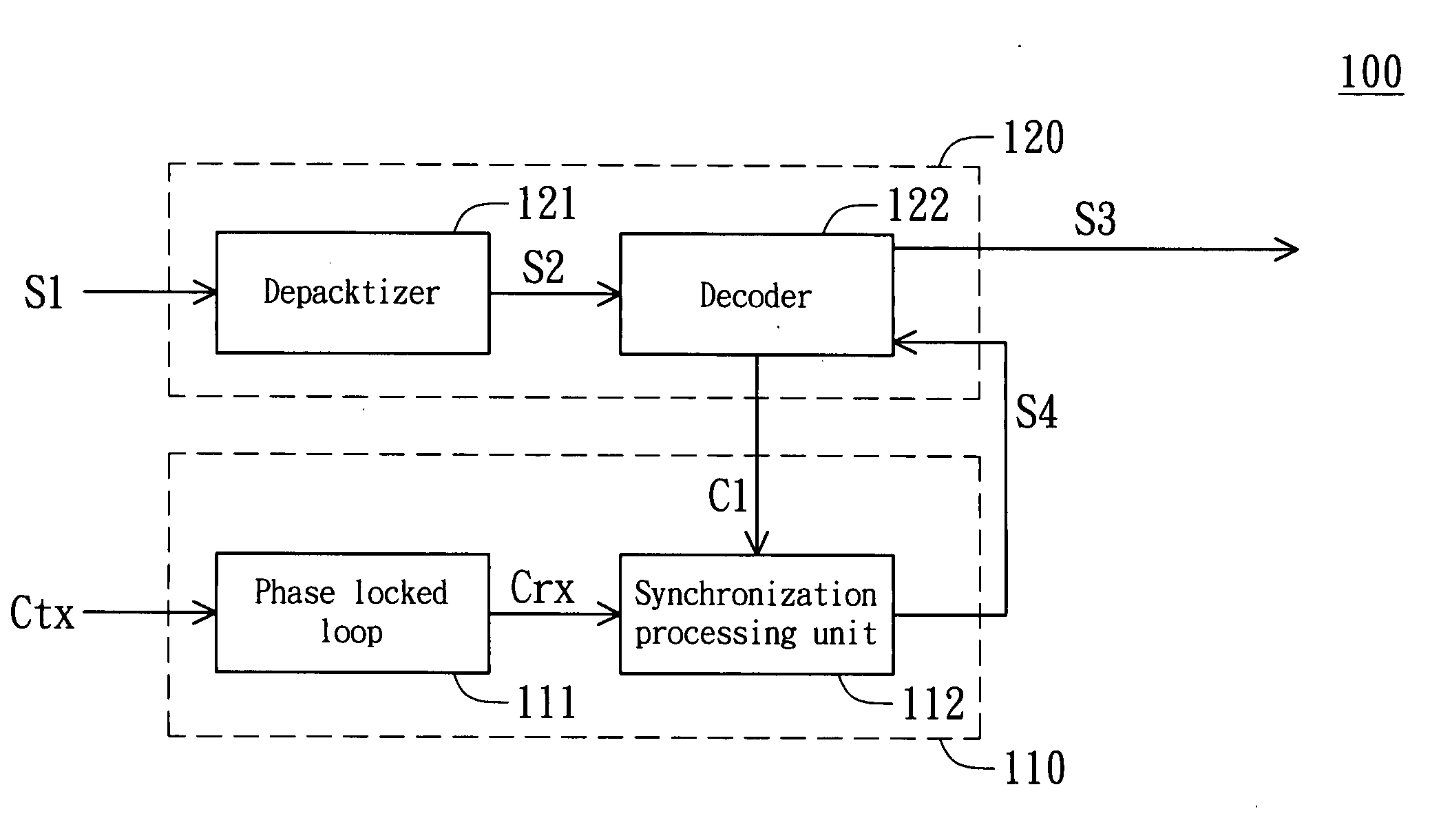
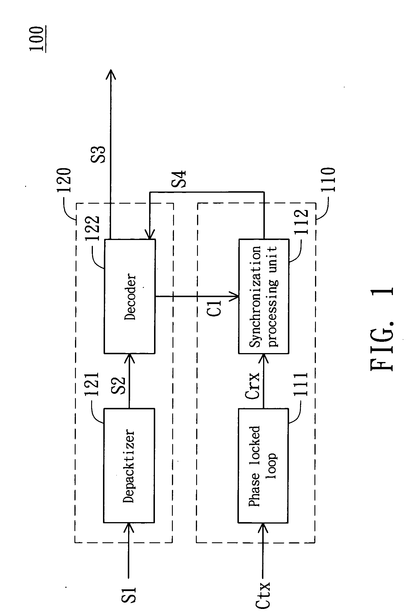
[0016] Referring to FIG. 1, a block diagram of a reception module according to the invention is shown. The reception module 100 includes a timing synchronization module 110 and a signal processing module 120. The timing synchronization module 110, for controlling the playing of media signals S3, includes a phase locked loop (PLL) and a synchronization processing unit 112. The PLL 111 is for receiving output-end clock signals Ctx. When the PLL 111 receives the output-end clock signal Ctx for the first time, the PLL 111 generates a reception-end clock signal Crx according to the output-end clock signal Ctx. The synchronization processing unit 112 is for receiving a procedure clock signal C1 and the reception-end clock signal Crx. The signal processing module 120 includes a depacketizer 121 and a decoder 122. The depacketizer 121 receives a packet signal S1 and outputs a depacketized signal S2. The decoder 122 receives and decodes the depacketized signal S2, and then outputs the media ...

second embodiment

[0022] Referring to FIG. 4, a flow chart of the method for synchronously playing media signals used in the reception module 200 according to the invention is shown. First, in step 41, receive an output-end clock signal Ctx. Afterward, in step 42, determine whether the output-end clock signal Ctx is received for the first time. If yes, go to step 43 to generate a reception clock signal Crx according to the output-end clock signal Ctx and return to the step 41. If not, go to step 44 to determine the relationship among the difference value K of M and N, the first preset value Th1 and the second preset value Th2. The output-end clock signal Ctx has M pulses after the reception-end clock signal is generated while the reception-end clock signal has N pulses as generated. The first preset value Th1 is larger than the second preset value Th2.

[0023] When the difference value K is larger than the first preset value Th1, go to step 45 to remove the media signal S3 corresponding to the procedur...


PUM


Abstract

The timing synchronization module includes a phase locked loop (PLL) and a synchronization processing unit. The PLL receives an output-end clock signal. When the PLL receives the output-end clock signal for the first time, the PLL generates a reception-end clock signal according to the output-end clock signal. The synchronization processing unit receives a procedure clock signal and the reception-end clock signal. The output-end clock signal has M clocks after the reception-end clock signal is generated, while the reception-end clock signal has N clocks as generated. When the difference value of M and N is larger than a preset value, the synchronization processing unit removes the media signal corresponding to the procedure clock signal and generates the reception-end clock signal again. When the difference value is smaller than the preset value, the synchronization processing unit controls media signal playing according to the reception-end clock signal and the procedure clock signal.

Description

[0001] This application claims the benefit of Taiwan application Serial No. 94107379, filed Mar. 10, 2005, the subject matter of which is incorporated herein by reference. BACKGROUND OF THE INVENTION [0002] 1. Field of the Invention [0003] The invention relates in general to a timing module and method for playing a media signal, and more particularly to a timing synchronization module and method for synchronously playing a media signal. [0004] 2. Description of the Related Art [0005] Wireless broadband network has stepped into a widespread stage, and is applied in international airports, hotels, restaurants, coffee chains for instance. The users can just roam leisurely in network world by inserting wireless local area network (LAN) cards into their notebook computers or personal digital assistants (PDAs). Network resources can therefore be rapidly and conveniently retrieved and applied without space limitation. [0006] In a real-time encoder system, using wireless broadband technolog...

Claims


Application Information

Patent Timeline
Patent Type & Authority Applications(United States)
IPC IPC(8): H03K11/00
CPCH04N21/4305H04N21/6131
Inventor CHIN, YI-LONLEE, CHANG-HUNG
Owner QUISDA CORP
Why Eureka
Try Eureka