
Design rule report utility

a technology of design rules and report utility, applied in the field of software tools, can solve the problems of human engineers entering the design rules, prone to typographical errors, and no longer using tape and cardboard in the design of circuit boards

Inactive Publication Date: 2006-09-28
MOTOROLA SOLUTIONS INC
View PDF6 Cites 23 Cited by
  • Summary
  • Abstract
  • Description
  • Claims
  • Application Information

AI Technical Summary

Problems solved by technology

Today, however, tape and cardboard are no longer used in designing circuit boards.
The problem with this system is that the engineers who enter the design rules are human.
Consequently, they are prone to make typographical errors when entering the design rules.
This is incredibly time consuming, however, as such a text file can exceed one hundred pages for even the simplest schematic.
With typical design cycles running less than six weeks, there is simply not enough time to read and hand check hundreds and hundreds of pages of textual data.

Method used


Image

  • Design rule report utility
  • Design rule report utility
  • Design rule report utility

Examples


Embodiment Construction

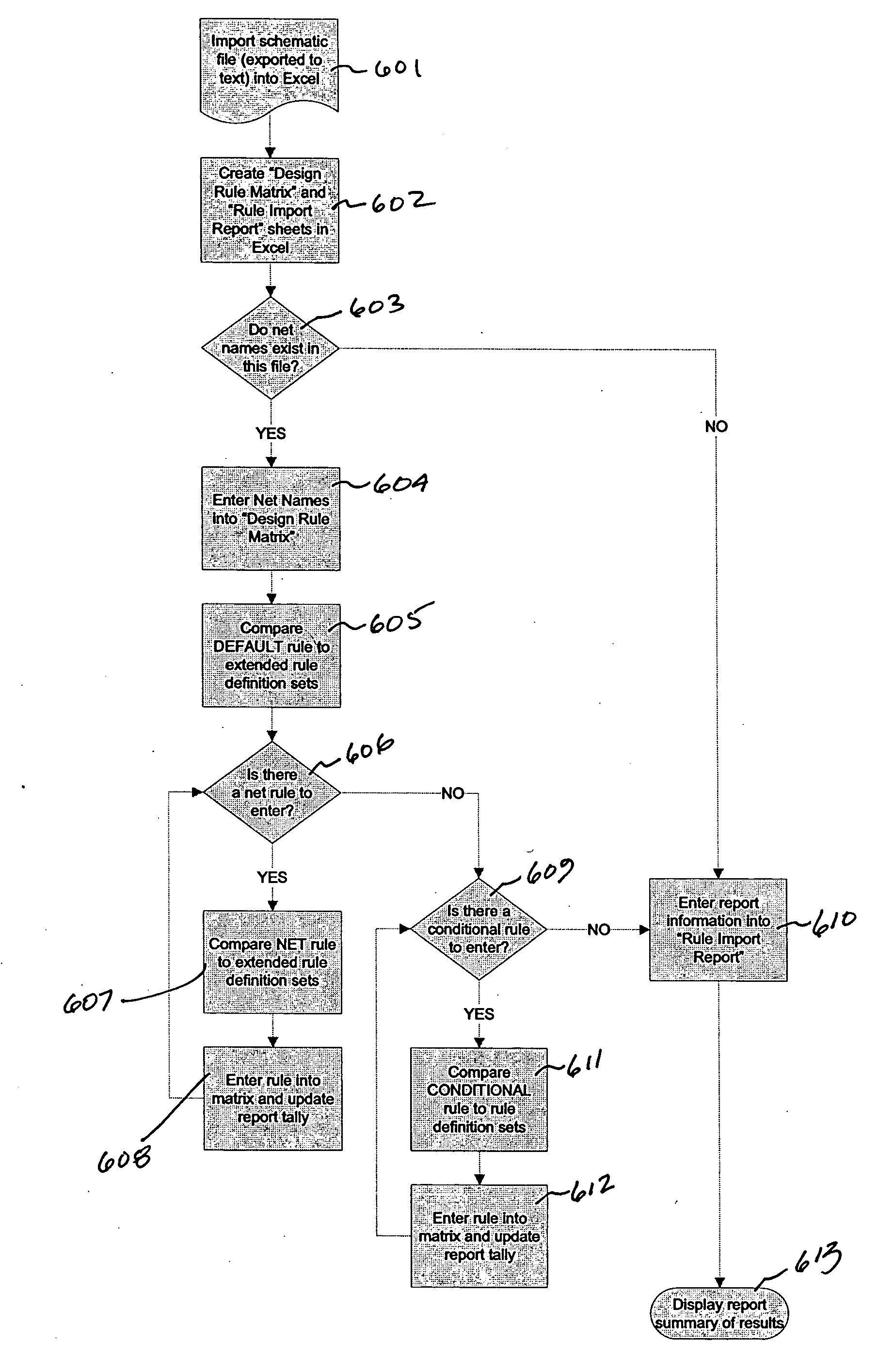
[0022] A preferred embodiment of the invention is now described in detail. Referring to the drawings, like numbers indicate like parts throughout the views. As used in the description herein and throughout the claims, the following terms take the meanings explicitly associated herein, unless the context clearly dictates otherwise: the meaning of “a,”“an,” and “the” includes plural reference, the meaning of “in” includes “in” and “on.”

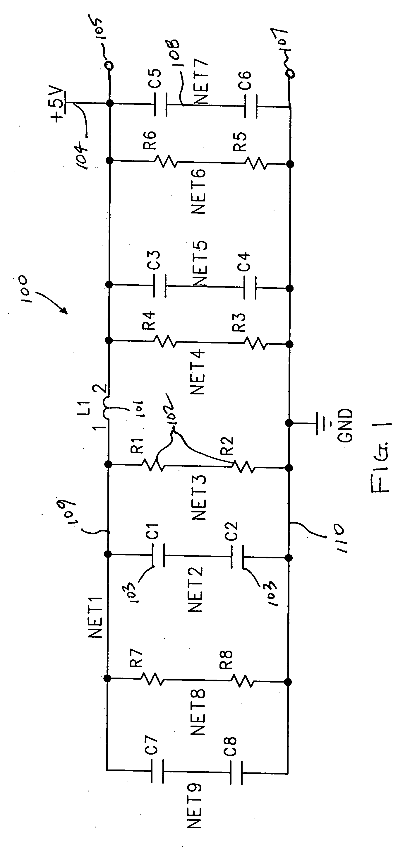
[0023] In its simplest embodiment, this invention includes a method for graphically displaying relational information between sets of data elements that correspond to an electronic model. For example, using an electrical circuit computer aided design package for schematic capture and printed circuit board layout, the invention imports design rules from a schematic capture program. The design rules may relate to, for example, a series of electrical connections or nets. These design rules are then displayed as a matrix for easy validation and verification...


PUM


Abstract

This invention provides a graphical tool by which a designer or engineer may quickly, accurately and efficiently check the relational information between elements of a computer model. By way of example, in one embodiment, the invention may be used to quickly validate the design rules, like minimum spacing requirements for instance, between the connections (or nets) in a schematic that exists in a computer aided design package. Since a designer must enter such design rules for each net, the invention first imports these design rules from the computer model. The invention then imports a standard set of design rules. After comparing the standard set of design rules to the standard set of design rules, the invention presents a graphical display to a user indicating where the model rules matched the standard set and, correspondingly, where they did not match. In one embodiment, a matrix grid is displayed with the model elements listed in an index row and column. Matches are then displayed as coefficients within the matrix, while mismatches are displayed as an alternate coefficient. The invention allows a designer to quickly identify data entry errors that may have occurred in the creation of the model.

Description

BACKGROUND [0001] 1. Technical Field [0002] This invention relates generally to a software tool for rapidly checking design rules associated with an apparatus or computer model, and more specifically to software that compares relational data of an apparatus or software model to a set of predetermined design rules and graphically presents to a user a matrix that indicates where the relational data does and does not correspond to those design rules. [0003] 2. Background Art [0004] Most all electronic devices include a printed circuit board somewhere in the device. The printed circuit board serves as the “brain” of the device, as this is where all of the electronic “magic” happens. Microprocessors, memory devices, transistors, resistors and capacitors are all connected together on the printed circuit board. In short, in an electronic device, a printed circuit board is where all the action takes place. [0005] Not so long ago, engineers designed printed circuit boards using tape and card...

Claims


Application Information

Patent Timeline
IPC IPC(8): G06F17/50G09G5/00
CPCG06F17/5081G06F30/398
Inventor MCLAIN, MICHELLE A.KREISINGER, ROBERT D.PETERSON, ALBERT D.
Owner MOTOROLA SOLUTIONS INC
Learn More