Heat energy recovery apparatus

a technology of heat energy recovery and heat energy, which is applied in the direction of steam accumulator, hot gas positive displacement engine plant, steam engine plant, etc., can solve the problems of thermal energy recovery efficiency degradation, thermal energy recovery efficiency degradation, and expansion loss generation in the expander, so as to suppress the degradation of thermal energy recovery efficiency and improve conventional drawbacks

Inactive Publication Date: 2006-10-05
TOYOTA JIDOSHA KK
View PDF15 Cites 70 Cited by
  • Summary
  • Abstract
  • Description
  • Claims
  • Application Information

AI Technical Summary

Benefits of technology

[0010] Consequently, the present invention is to improve such conventional drawbacks and it is an object of the present invention to provide a heat energy recovery apparatus capab

Problems solved by technology

However, in the aforementioned heat cycle engine, if the engine works regardless that required engine output is low, output taken out with the work wastes, resulting in bringing degradation in recovery efficiency of thermal energy.
For this reason, if the Brayton cycle engine works when heat receiving capacity of the working

Method used


Image

  • Heat energy recovery apparatus
  • Heat energy recovery apparatus
  • Heat energy recovery apparatus

Examples


first embodiment

[0036] A heat energy recovery apparatus according to the present invention will be described with reference to FIG. 1 to FIG. 7.

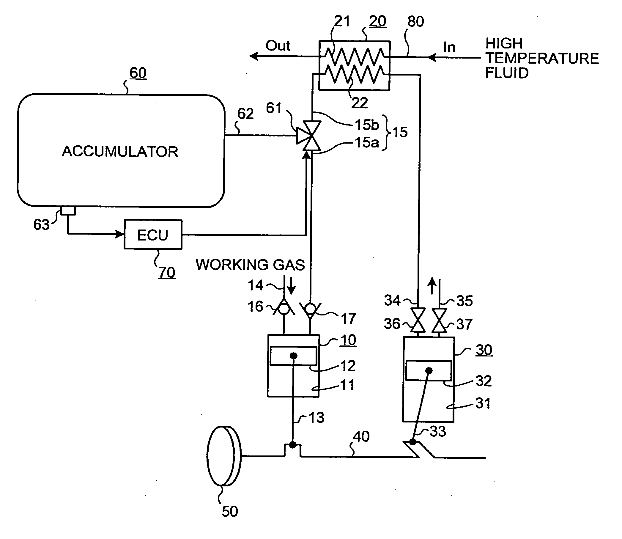
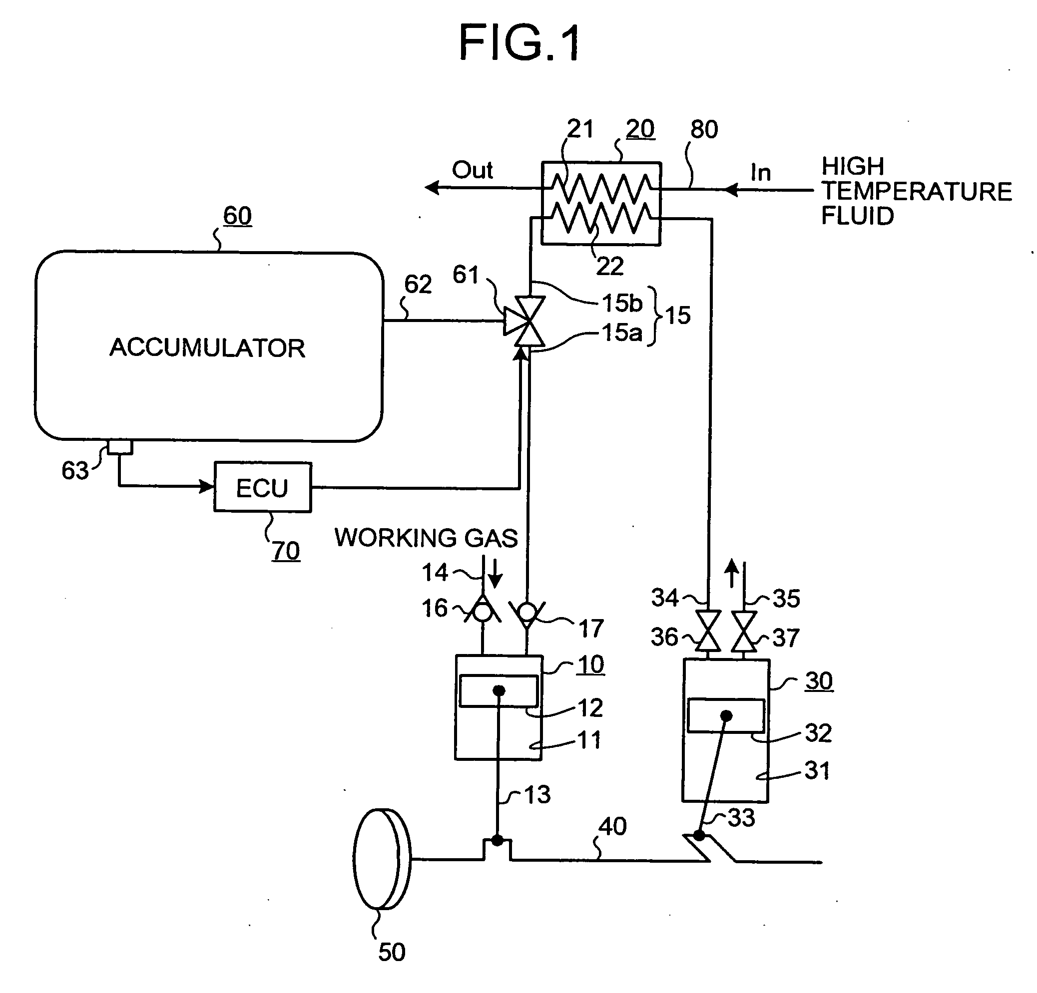
[0037] The heat energy recovery apparatus of the first embodiment is a Brayton cycle engine in which working fluid is processed using heat of high temperature fluid as follows: adiabatic compression→isobaric heat receiving→adiabatic expansion→isobaric heat radiation, thereby obtaining driving force. As shown in FIG. 1, the heat energy recovery apparatus includes a compressor 10 which adiabatically compresses suck-in working fluid, a heat exchanger 20 which makes the working fluid adiabatically compressed by the compressor 10 absorb heat of high temperature fluid under isobaric pressure, and an expander 30 which makes the working fluid isobarically heat-received by the heat exchanger 20 expand adiabatically.

[0038] Here, exhaust gas discharged from an internal combustion engine (not shown in the figure) is used as the high temperature fluid and exhaust heat ...

second embodiment

[0090] A heat energy recovery apparatus according to the present invention will be described with reference to FIG. 8 to FIG. 9B. In addition, also here, an exhaust heat recovery apparatus which recovers exhaust heat of an internal combustion engine (not shown in the figure) is exemplified as the heat energy recovery apparatus.

[0091] The exhaust heat recovery apparatus according to the second embodiment, in the exhaust heat recovery apparatus of the aforementioned first embodiment, is one in which pumping loss of the expander 30, which generates in storing the compressed working gas to the accumulator 60, is reduced.

[0092] Here, an enlarged view of the pumping loss of the expander 30 in FIG. 3 is shown in FIG. 9A. The reference character “P1” shown in FIG. 3 and FIG. 9A denotes atmospheric pressure and “Pa” denotes negative pressure. Furthermore, the reference character “Vo” denotes a volume of the expander 30 when the piston 32 is located at the top dead center; and “Vexp” denotes...


PUM


Abstract

A heat energy recovery apparatus include a compressor which has a piston for compressing sucked-in working gas; a heat exchanger which makes the working gas compressed by the compressor absorb heat of high temperature fluid; an expander which has a piston to be moved under pressure by expansion of the heat-absorbed working gas; and an accumulator which stores the working gas compressed by the compressor when required output is low or heat receiving capacity of the working gas is small. The apparatus preferably include a blocking unit which blocks discharge of the working gas from the expander when the heat receiving capacity of the working gas is small and the compressed working gas to the accumulator is being stored.

Description

BACKGROUND OF THE INVENTION [0001] 1. Field of the Invention [0002] The present invention relates to a heat energy recovery apparatus for converting thermal energy in which heat is absorbed by a heat exchanger to mechanical energy. [0003] 2. Description of the Related Art [0004] Conventionally, there exists a heat cycle engine that converts thermal energy to mechanical energy. [0005] For example, as this kind of a heat cycle engine, there is a Brayton cycle engine which includes a compressor which adiabatically compresses sucked-in working fluid (working gas), a heat exchanger which makes the working gas adiabatically compressed by the compressor absorb heat of high temperature fluid under isobaric pressure, and an expander which makes the working gas isobarically heat-received by the heat exchanger expand adiabatically; and which takes out output from a crankshaft using the expansion force, as disclosed in Japanese Patent Application (JP-A) Laid-Open No. 6-257462. [0006] As describ...

Claims


Application Information

Patent Timeline
IPC IPC(8): F01K3/00F01K1/00
CPCF01K3/006F01K7/36F01K3/02
Inventor MITANI, SHINICHI
Owner TOYOTA JIDOSHA KK
Why Eureka
Try Eureka