Method for injecting a liquid mist into an intake duct

Inactive Publication Date: 2006-10-05
ANSALDO ENERGIA IP UK LTD
View PDF10 Cites 25 Cited by
  • Summary
  • Abstract
  • Description
  • Claims
  • Application Information

AI Technical Summary

Benefits of technology

[0004] It is therefore an object of the present invention to provide for

Problems solved by technology

Switching operations of this type lead to hammers in the injection systems and associated pipeline systems which may put the integrity of the system at risk and/or

Method used


Image

  • Method for injecting a liquid mist into an intake duct
  • Method for injecting a liquid mist into an intake duct
  • Method for injecting a liquid mist into an intake duct

Examples


Example

[0016] Elements not directly necessary for understanding the invention are omitted. The exemplary embodiments are to be understood purely instructively and are not to be called upon in order to restrict the invention characterized in the claims.

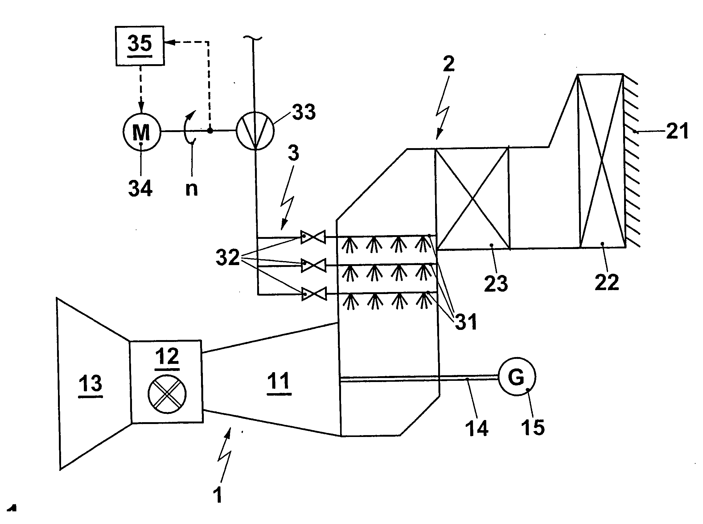
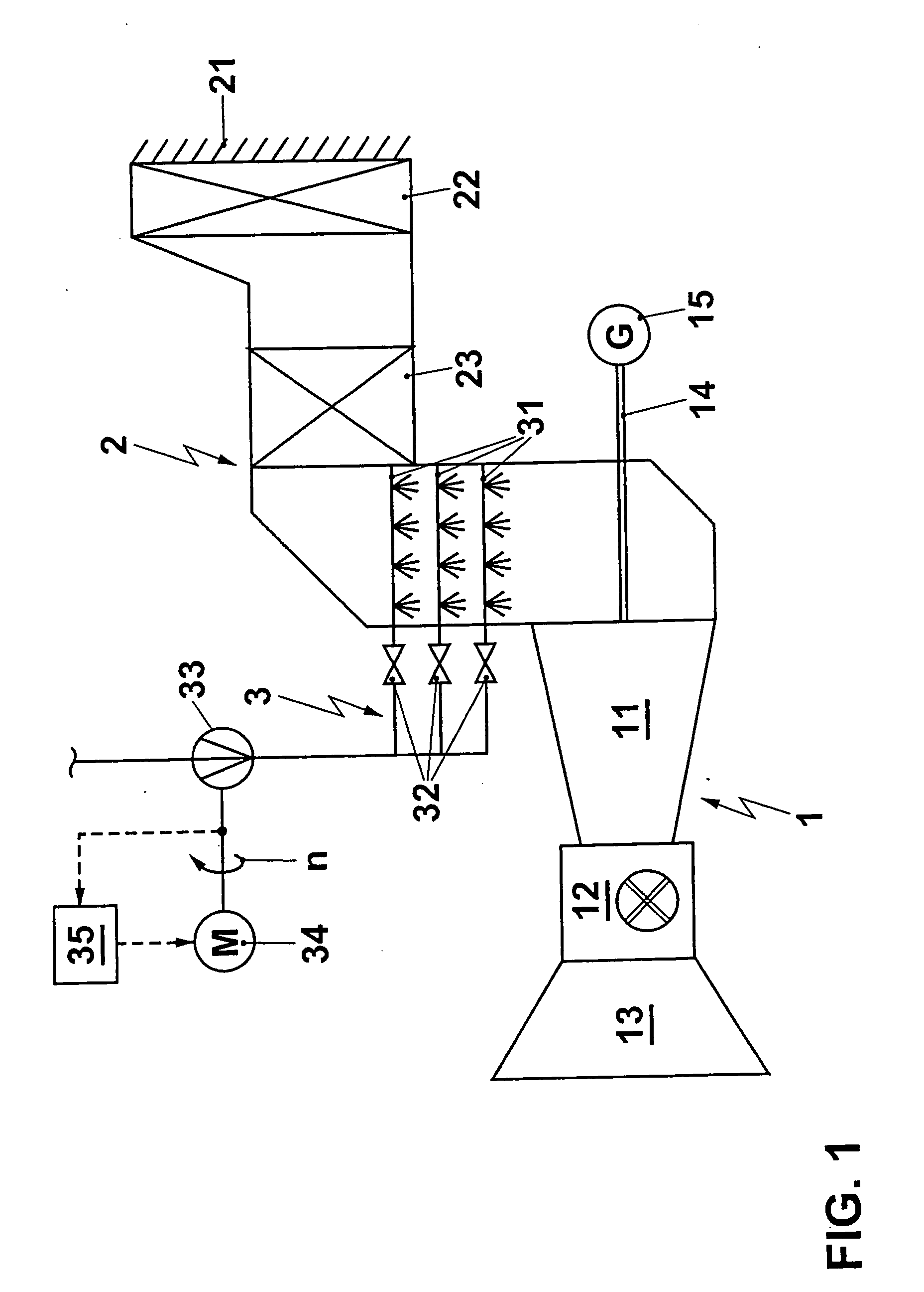
[0017]FIG. 1 illustrates a gas turbo set 1 comprising a compressor 11, a combustion chamber 12 and a turbine 13. The gas turbo set drives a generator 15 via a shaft 14. An air intake duct 2 is arranged upstream of the compressor 11. At the air inlet of this duct are arranged weather protection slats 21, followed by an air filter 22 and by a muffler 23. Furthermore, an atomization and injection system 3 for a liquid to be sprayed as a liquid mist into the intake duct is arranged. This comprises nozzle tubes 31 which are arranged in the intake duct 2 and carry atomizer nozzles. The nozzle tubes 31 are provided with injection nozzles, not explicitly illustrated but readily familiar to a person skilled in the art, and serve for feeding the latte...


PUM


Abstract

A system for the atomization of liquid is arranged on the intake duct of a gas turbo set. This atomization system comprises a number of nozzle tubes with atomizer nozzles, switching valves for selective action upon the nozzle tubes by liquid and a pump for conveying the liquid to be atomized. According to the invention, the pump is connected to a variable-speed drive. The switching valves are preferably designed as proportional valves. In a corresponding regulating circuit, this makes it possible to limit pressure gradients in the atomization system and consequently to avoid hammers.

Description

RELATED APPLICATION [0001] This application claims priority under 35 U.S.C. §119 to German Application No. 103 40 177.6 filed in Germany on Sep. 1, 2003, and as a continuation application under 35 U.S.C. §120 to PCT / EP2004 / 051928 filed as an International Application on Aug. 26, 2004, designating the U.S., the entire contents of which are hereby incorporated by reference.BACKGROUND INFORMATION [0002] The injection of liquid into the intake duct of air-breathing thermal engines is known in the prior art as a means of increasing the power. In FR 1,563,749, DE 25 49 790 or EP 898645, it was proposed, for example, to inject liquid water droplets into a compressor of a gas turbo set. [0003] Often, in this case, injection systems are used in which switching valves switch on nozzles or nozzle groups or in which the throughflow is controlled by valves, the characteristic curve of which deviates sharply from the linearity of the throughflow behavior against the valve position. This is the ca...

Claims


Application Information

Patent Timeline
IPC IPC(8): F02C3/30F02C7/143F04D29/58F04D29/70
CPCF02C7/1435F04D29/705F04D29/5846
Inventor HAERTEL, CARLOS JIMENEZOESTERLE, STEFANREUMSCHUESSEL, CARSTENSAVIC, SASHA
Owner ANSALDO ENERGIA IP UK LTD
Why Eureka
Try Eureka