Endurance testing apparatus

a technology of endurance test and test specimen, which is applied in the direction of instruments, structural/machine measurement, force measurement, etc., can solve the problems of spoiled accuracy of endurance test, difficult temperature control, and unsuitable high-frequency reciprocating rig for endurance test specimens, etc., and achieve the effect of reducing time and cost for performing

Inactive Publication Date: 2006-10-05
DENSO CORP +1
View PDF6 Cites 8 Cited by
  • Summary
  • Abstract
  • Description
  • Claims
  • Application Information

AI Technical Summary

Benefits of technology

[0009] The present invention is achieved in view of the above-described issues, and has an object to provide an endurance testing apparatus that is suitable for performing an endurance test

Problems solved by technology

Thus, the high frequency reciprocating rig is not suitable for the endurance test of the test specimen such as a fuel injection valve, in which a first member and a second member such as a nozzle body and a needle of a fuel injection valve repeats contacting with and separating from each other.
Further, the testing medium fluid J3 is received in the opened vessel J4, so that it is difficult to control the temperature of the testing medium fluid J3 with accuracy.
The temperature of the testing medium fluid J3 affects the abrasion amount, so that the accuracy of the endurance test is spoiled.
As described above, the high frequency reciprocating rig is not suitable for the endurance test of the test specimen such as a fuel injection valve, in which the first member and the second member repeats contacting with and separating from each other.
Firstly, the endurance testing apparatus incorporates an actual internal combustion engine.
This increases the size and cost of the endurance testing apparatus, and it is difficult to perform a large number of endurance tests by this endurance testing appar

Method used


Image

  • Endurance testing apparatus
  • Endurance testing apparatus
  • Endurance testing apparatus

Examples


first embodiment

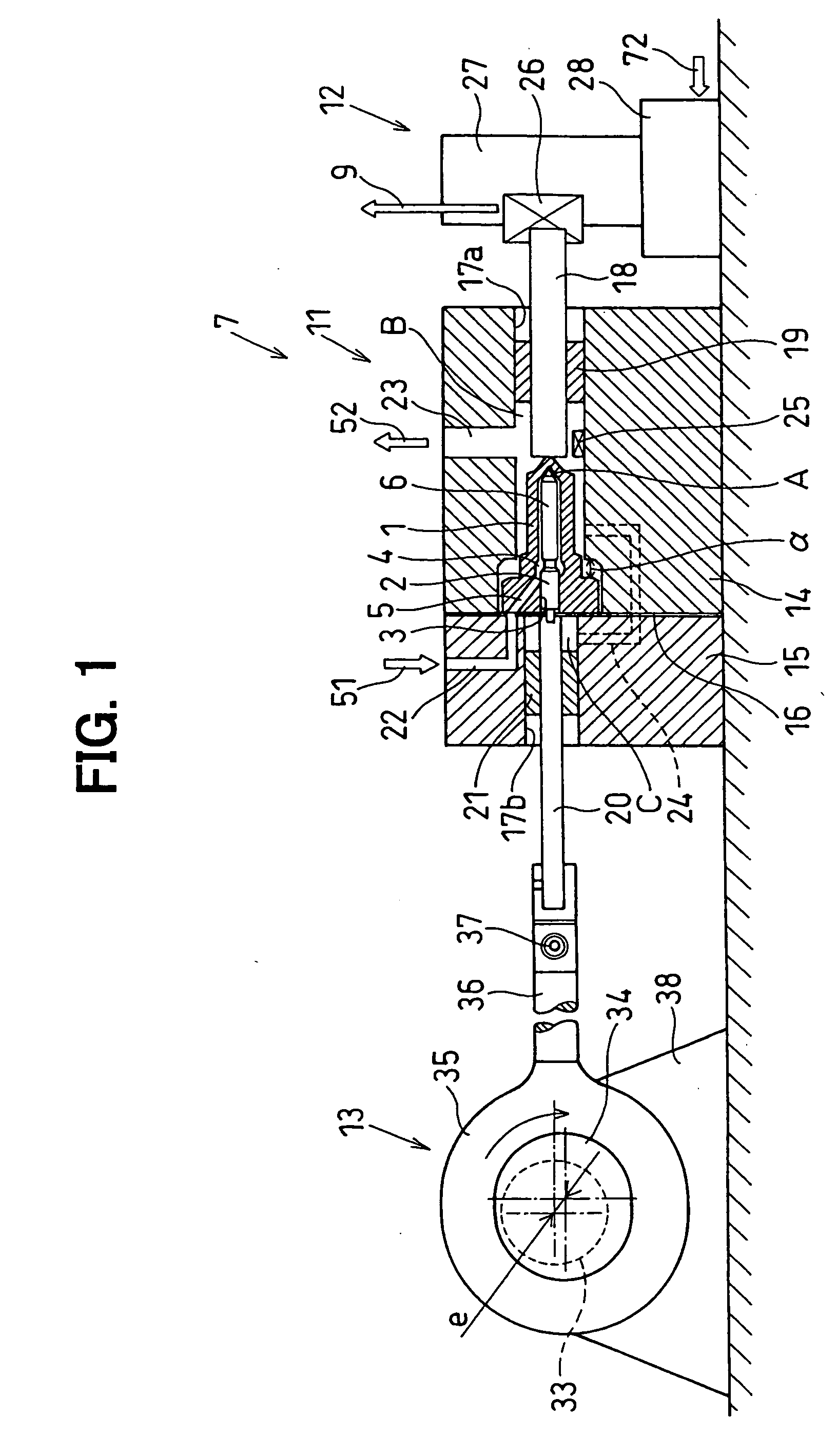
[0027] An endurance testing apparatus according to the first embodiment is described in the following, referring to FIGS. 1 to 10.

[0028] The endurance testing apparatuses in the first to fourth embodiments are for performing an endurance test of a nozzle assembly in a fuel injection valve. The fuel injection valve is an example of a test specimen in which a first member and a second member repeatedly come in contact with and apart from each other. In the first to third embodiments, the endurance testing apparatuses performs the endurance test adopt by using low critical fuel such as alcohol fuel, which is easily vaporized at normal temperature and normal pressure.

[0029] Firstly, the nozzle assembly, of which the endurance is tested by the endurance testing apparatus, is described in the following.

[0030] The nozzle assembly is for starting and stopping fuel injection in the fuel injection valve, which injects fuel in an internal combustion engine, and formed from a nozzle body 1 a...

second embodiment

[0172] An endurance testing apparatus according to the second embodiment is described in the following, referring to FIG. 11. In the following embodiments, the referential numerals assigned as same as in the first embodiment substantially represents the components that have functions substantially the same as those in the first embodiment. In the following embodiments, the differences from the first embodiment are described.

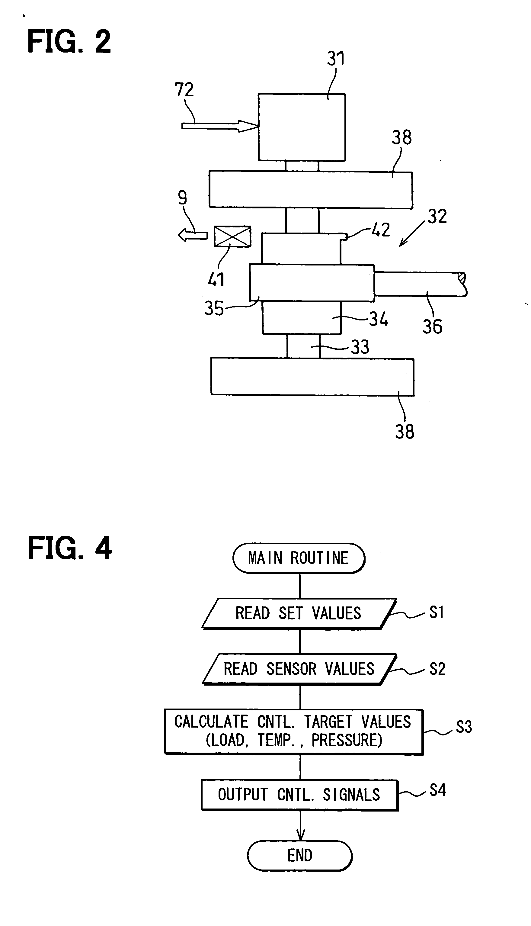
[0173] In the above-described first embodiment, the contact load Fi between the nozzle body 1 and the needle 2 is detected by the load sensor 26 interposed between the load shaft 18, which is in contact with the leading end of the nozzle body 1 and the sensor support block 27. The adjusting device 28 moves the sensor support block 27 in the axial direction to adjust the contact load Fi between the nozzle body 1 and the needle 2.

[0174] In the second embodiment, the load sensor 26 is located on the way of the drive shaft 20, which is for reciprocating the needle ...

third embodiment

[0181] An endurance testing apparatus according to the third embodiment is described in the following, referring to FIG. 12.

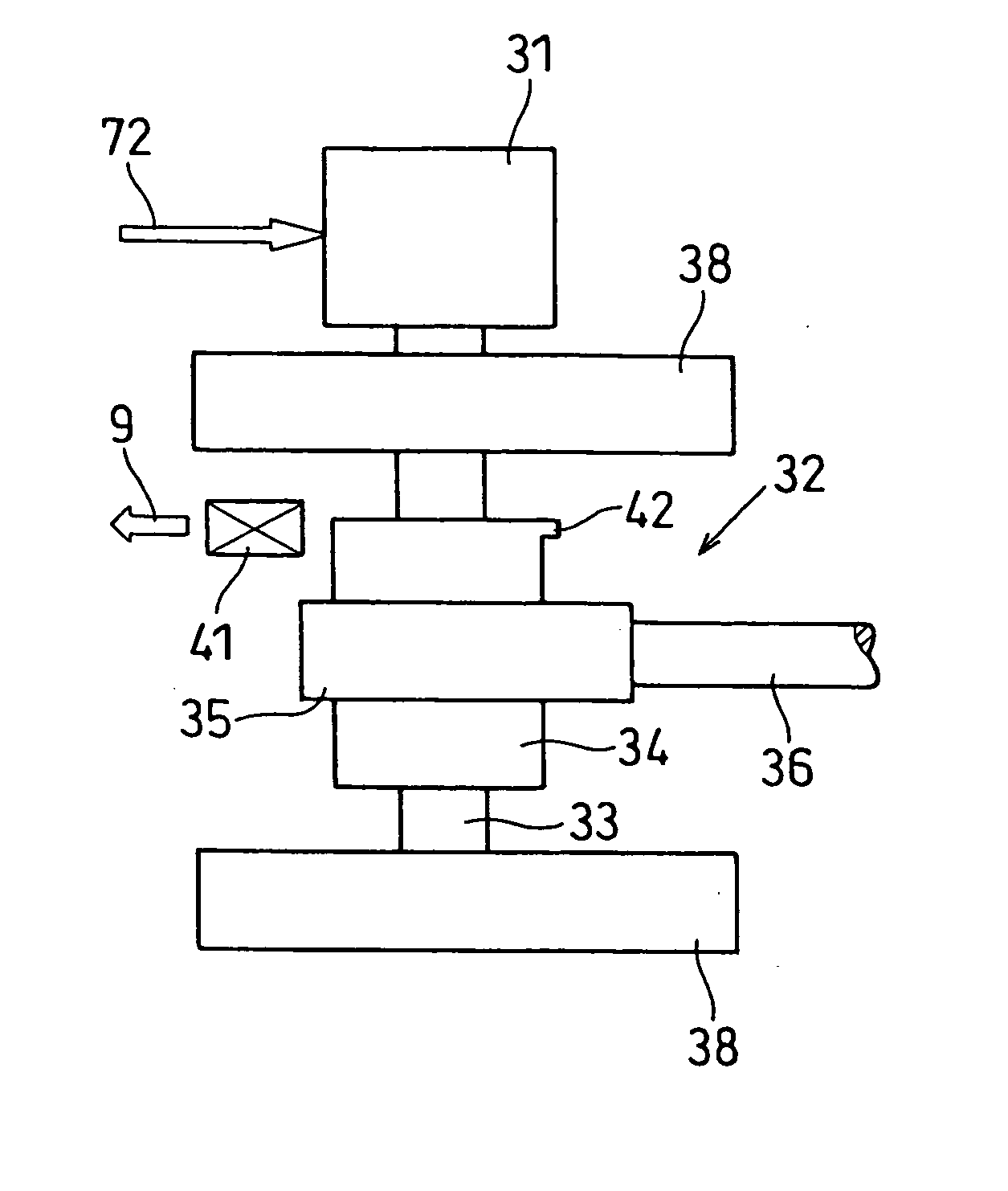
[0182] In the above-described first embodiment, the contact load generator 13 of the testing apparatus body 7 reciprocates the needle 2 in the axial direction.

[0183] In the third embodiment, the testing apparatus body 7 is provided with a rotating means 73, which rotates the needle 2 relative to the needle body 1, in addition to the contact load generator 13.

[0184] That is, in the third embodiment, the testing apparatus body 7 can rotate the needle 2 by the rotating means 73 in reciprocating the needle 2 by the contact load generator 13 in the axial direction.

[0185] In the third embodiment, the rotating means 73 rotates the drive shaft 20 in combination with the contact load generator 13. In the third embodiment, the drive shaft 20 is rotatably installed. Specifically, in the third embodiment, a second joint 74 is provided between the drive shaft 20 and the...


PUM


Abstract

An endurance testing apparatus, which is for performing an endurance test of a contacting/separating portion in which a first member and a second member repeats contacting with and separating from each other, has a contact load generator and a testing medium fluid supply means. The contact load generator reciprocates the second member relative to the first member to generate a contact load acting between the first member and the second member repeatedly. The testing medium fluid supply means supplies a testing medium fluid to the contacting/separating portion to expose the first member and the second member to the testing medium fluid.

Description

CROSS REFERENCE TO RELATED APPLICATION [0001] This application is based upon and claims the benefit of priority of Japanese Patent Applications No. 2005-102863 filed on Mar. 31, 2005 and No. 2006-012703 filed on Jan. 20, 2006, the contents of which are incorporated herein by reference. FIELD OF THE INVENTION [0002] The present invention relates to an endurance testing apparatus for evaluating endurance of a mechanical device, especially to the endurance testing apparatus for performing an endurance test of a contacting / separating portion in which a first member and a second member of the mechanical device repeats contacting with and separating from each other in a testing medium fluid. BACKGROUND OF THE INVENTION [0003] High frequency reciprocating rig (HFRR), which is schematically shown in FIG. 15, is known as a general endurance testing apparatus. The high frequency reciprocating rig reciprocates a test specimen ball J1 at high frequency in pushing the test specimen ball J1 onto ...

Claims


Application Information

Patent Timeline
IPC IPC(8): G01B7/16G01M99/00
CPCG01N3/56G01N2203/0242G01N2203/0037G01N2203/0005
Inventor KATO, MASAAKIFUTAMURA, MAIKOMIYAGAWA, HIROSHI
Owner DENSO CORP
Why Eureka
Try Eureka