Footswitch operable to control a surgical system

a surgical system and footswitch technology, applied in the field of surgical footswitch, can solve the problems of improper control inputs, tethers, wires and cables that have the potential to injure patients, and achieve the effect of removing the possibility of failure of the footswitch

Active Publication Date: 2006-10-05
ALCON INC
View PDF21 Cites 108 Cited by
  • Summary
  • Abstract
  • Description
  • Claims
  • Application Information

AI Technical Summary

Benefits of technology

[0008] One embodiment provides a surgical footswitch having a base, a pedal, an encoder assembly, and a wireless interface. The pedal mounts upon the base and pivots. The encoder assembly couples to the pedal. As the pedal pivots, the encoder assembly translates the mechanical signal of the pedal into a control signal based on the pedal's position and/or orientation. The wireless interface couples the encoder assembly to receive the control signal. The wireless interface also couples the surgical footswitch to a surgical console operable to control and direct surgical equipment. The wireless interface passes the control signal from the encoder to the surgical console, which then directs the surgical equipment based on the control s...

Problems solved by technology

As the footswitches are moved about the operating room, these tethers, wires and cables can become tangled with other equi...

Method used


Image

  • Footswitch operable to control a surgical system
  • Footswitch operable to control a surgical system
  • Footswitch operable to control a surgical system

Examples


Embodiment Construction

[0021] Preferred embodiments of the present invention are illustrated in the FIGs., like numerals being used to refer to like and corresponding parts of the various drawings.

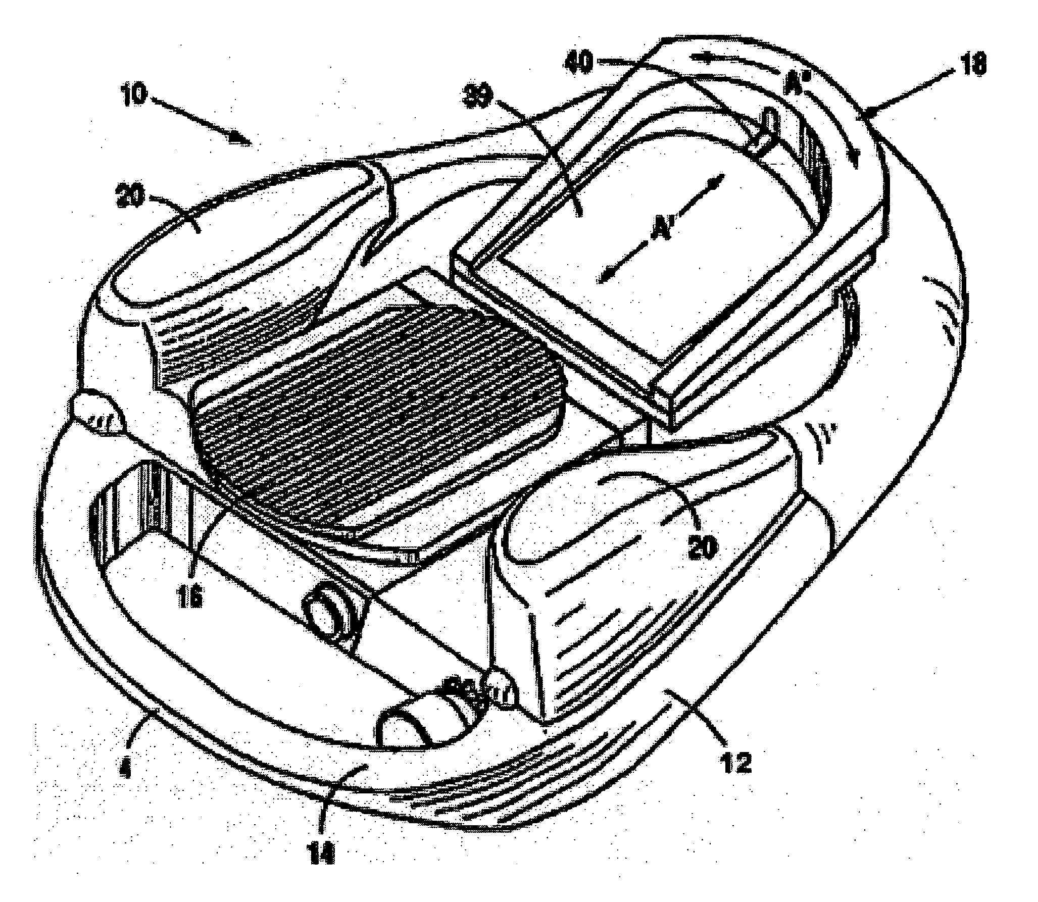
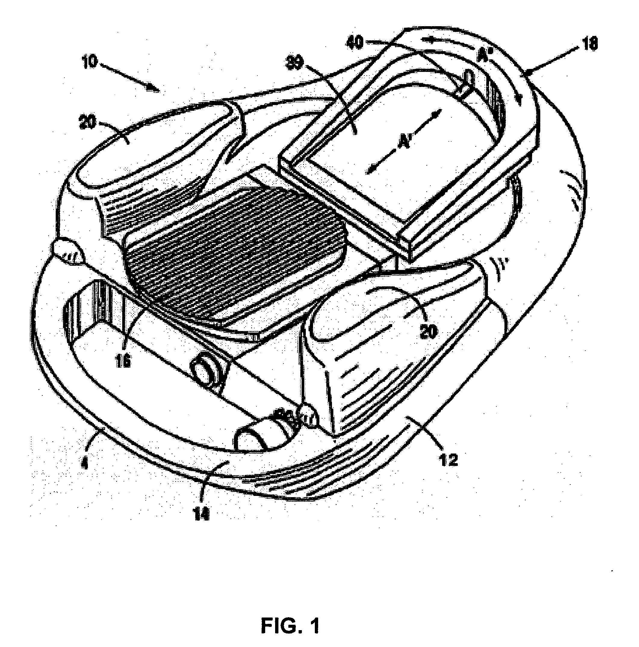
[0022]FIG. 1 depicts an embodiment of a footswitch assembly 10. The surgical footswitch assembly 10 includes a body or housing that further includes bottom housing 12 and top housing 14, and a foot pedal or treadle 16, all of which can be made from any suitable material, such as stainless steel, titanium or plastic. Other embodiments may additionally include a separate heel cup assembly 18 and a handle 4 positioned in the front. Side or wing switches 20 may be placed on the top of housing 14 on either side of the foot pedal 16.

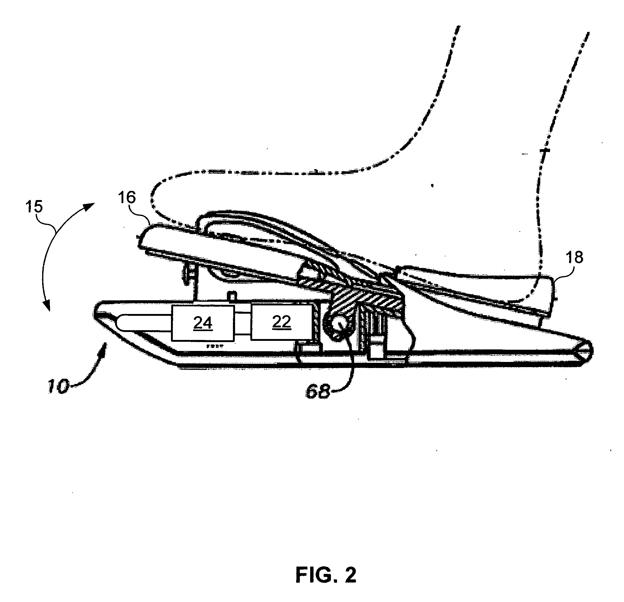
[0023] Attached to the foot pedal or tillable treadle 16 is an encoder assembly 22 as illustrated in the cross section provided by FIG. 2. Encoder assembly 22 translates the angular or pitch position of the foot pedal or treadle 16, which is tillable with respect to a horizontal plane or...


PUM


Abstract

The present invention provides a surgical footswitch that includes a base, a pedal, an encoder assembly, a wireless interface, and an internal power generator. The pedal mounts upon the base and pivots. The encoder assembly couples to the pedal. As the pedal pivots, the encoder assembly translates the mechanical signal of the pedal into a control signal based on the pedals position and/or orientation. The wireless interface couples the encoder assembly to receive the control signal. The wireless interface also couples the surgical footswitch to a surgical console operable to control and direct surgical equipment. The wireless interface passes the control signal from the encoder to the surgical console, which then directs the surgical equipment based on the control signal. This wireless interface eliminates the tangle of wires or tethers, which may be a hazard in the surgical theater. The internal power generator translates footswitch movement into stored energy to eliminate potential failures of the footswitch during a procedure and overcome the need to replace batteries within the footswitch.

Description

CROSS-REFERENCE TO RELATED APPLICATIONS [0001] This application claims priority under 35 U.S.C. §119 to U.S. Provisional Patent Application No. 60 / 667,290, filed Mar. 31, 2005, the entire contents of which are incorporated herein by reference.TECHNICAL FIELD OF THE INVENTION [0002] The present invention relates generally to systems and methods for controlling a surgical system, and more particularly, to a surgical footswitch operable to securely, reliably, and wirelessly control a complex surgical system. BACKGROUND OF THE INVENTION [0003] During the use of a complex patient treatment apparatus or surgical system, for example, surgical equipment used when performing ophthalmic surgery, the control of a variety of different subsystems, such as pneumatic and electronically driven subsystems may be required. Typically, the operation of the subsystems is controlled by a microprocessor-driven console. The microprocessor controls within a surgical console receive mechanical inputs from ei...

Claims


Application Information

Patent Timeline
IPC IPC(8): G05G1/14G05G1/38
CPCA61B17/00Y10T74/2054A61B2017/00119A61B2017/00194A61B2017/00199A61B2017/00221A61B2017/00973A61C1/0023G05G1/38H01H21/26H01H2239/076H01H2300/014H01H2300/03Y02B70/3241Y04S20/227Y10T74/20888A61B19/5244A61B34/20Y02B70/30Y04S20/20
Inventor HORVATH, CHRISTOPHERBUCZEK, MARKROWE, T. SCOTT
Owner ALCON INC
Why Eureka
Try Eureka