
Papermaking belt

a technology of papermaking belts and belt loops, applied in the field of papermaking belts, to achieve the effect of superior strength

Inactive Publication Date: 2012-06-05
YAMAUCHI CORP
View PDF26 Cites 0 Cited by
  • Summary
  • Abstract
  • Description
  • Claims
  • Application Information

AI Technical Summary

Benefits of technology

[0013]It is an object of the present invention to provide a papermaking belt being free from voids and superior in terms of strength.
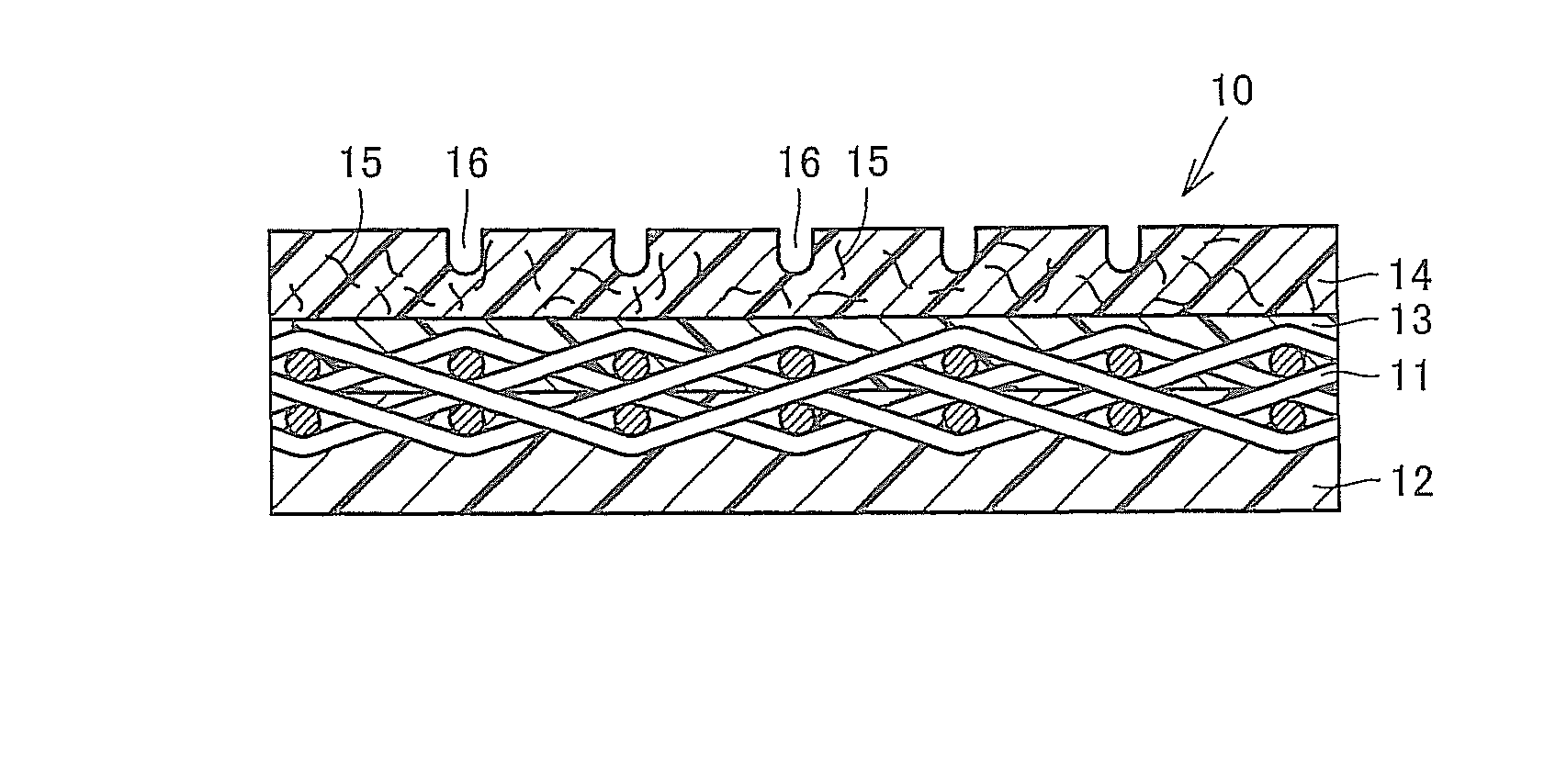
[0017]Since the second resin layer provided on the front surface side of the first resin layer has a higher viscosity than that of the first resin layer, and contains chopped fibers in a dispersed state, the strength is improved. Moreover, even if cracks are generated, spreading of the cracks can be suppressed by the chopped fibers. Moreover, in the case where drain grooves are formed in the surface of the second resin layer, the groove shape can be firmly maintained.
[0018]Preferably, the chopped fibers in the second resin layer are randomly oriented. Randomly orienting the chopped fibers eliminates the strength difference among the MD direction, the CD direction, and a thickness direction, whereby generation and spreading of cracks can be suppressed.
[0020]A content of the chopped fibers in the second resin layer is preferably in a range of 0.5% to 10% by mass. If the chopped fiber content exceeds 10%, the resin has an increased viscosity, and thus, has no flowability, causing a handling problem. If the chopped fiber content is lower than 0.5%, the reinforcing effect resulting from containing the fibers is less likely to be obtained.
[0021]In order to uniformly disperse the chopped fibers in the second resin layer, it is preferable to use chopped fibers subjected to a dispersive treatment, that is, RFL-treated or silanized chopped fibers. The use of such chopped fibers can eliminate tangling of the fibers. RFL treatment or silanization also improves the adhesive property between the chopped fibers and the resin.
[0022]In one embodiment, no fiber is contained in the first resin layer in order to facilitate penetration of the first resin layer into the base material layer. The first resin layer containing no fiber has a reduced viscosity, whereby the first resin layer penetrates into the base material layer in a desirable manner, and prevents voids from remaining in the base material layer. As another embodiment, fibers may be contained in the first resin layer to such a degree that can suppress the viscosity of the first resin layer to a low value.

Problems solved by technology

Such extension often causes cracks.

Method used


Image

  • Papermaking belt
  • Papermaking belt

Examples


Embodiment Construction

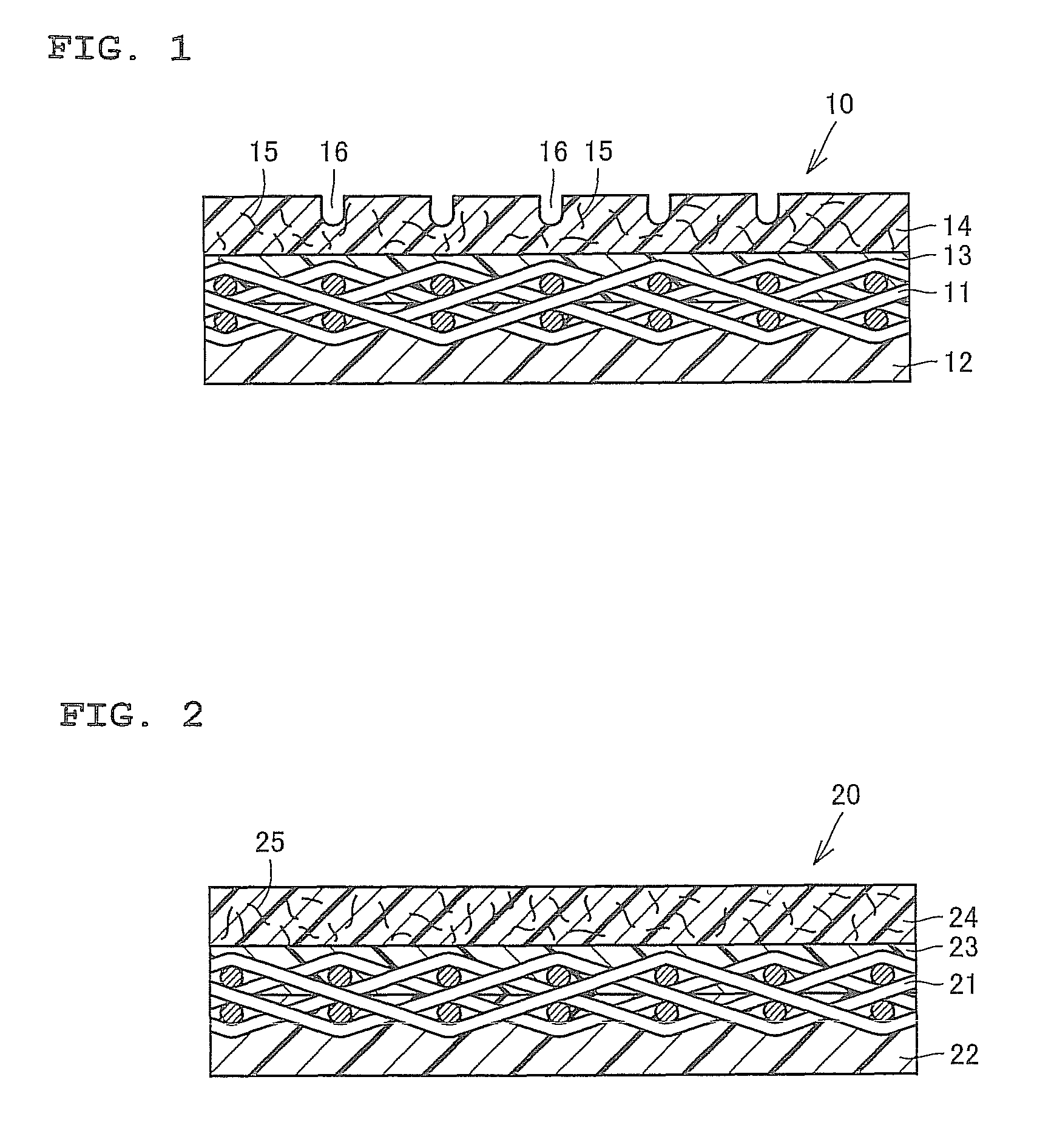
[0026]FIG. 1 is a cross-sectional view of a papermaking belt according to an embodiment of the present invention. A papermaking belt 10 of the present embodiment is a shoe press belt for use in a pressing / dehydrating process of a wet paper web. The papermaking belt 10 includes: a base material layer 11; a back-surface-side resin layer 12 which is provided on the back surface side of the base material layer, and at least a part of which has impregnated into the base material layer from the back surface side of the base material layer 11; a first resin layer 13 which has a relatively low viscosity, and has impregnated into the base material layer 11 from the front surface side of the base material layer; and a second resin layer 14 provided on the front surface side of the first resin layer 13.

[0027]The base material layer 11 includes longitudinal and lateral yarns. Since the papermaking belt 10 contains the base material layer 11 inside, the strength in a machine direction (MD direct...


PUM

PropertyMeasurementUnit
lengthaaaaaaaaaa
lengthaaaaaaaaaa
lengthaaaaaaaaaa

Abstract

A papermaking belt 10 includes: a base material layer 11 including longitudinal and lateral yarns; a back-surface-side resin layer 12 which is provided on a back surface side of the base material layer, and at least a part of which has impregnated into the base material layer from the back surface side of the base material layer; a first resin layer 13 which has a relatively low viscosity, and has impregnated into the base material layer 11 from a front surface side of the base material layer 11; and a second resin layer 14 which contains chopped fibers 15 in a dispersed state, has a higher viscosity than that of the first resin layer 13, and is provided on a front surface side of the first resin layer 13.

Description

TECHNICAL FIELD[0001]The present invention generally relates to a papermaking belt, and more particularly, to a shoe press belt for use in a dehydrating process of a wet paper web.BACKGROUND ART[0002]Examples of papermaking belts include a shoe press belt, a calendar belt, a transfer belt, and the like.[0003]General required characteristics for papermaking belts such as a shoe press belt include strength, crack resistance, abrasion resistance, flexibility, and impermeability to water, oil, gas, and the like. Polyurethane, which is obtained by a reaction between a urethane polymer and a curing agent, has been commonly used as a material having these characteristics.[0004]In a papermaking technique, it has been known to form a multiplicity of drain grooves, extending along a travel direction of a wet paper web, in the outer surface of a belt in order to drain water squeezed from the pressed wet paper web. For example, U.S. Pat. No. 4,559,258 describes a papermaking machine belt having...

Claims


Application Information

Patent Timeline
Patent Type & Authority Patents(United States)
IPC IPC(8): D21F3/02B32B5/02
CPCD21F3/0227D21F7/083D21F7/086Y10S162/901Y10T442/2057D21F3/00D21F7/08
Inventor MURAKAMI, TETSUYA
Owner YAMAUCHI CORP
Learn More