Micromixer apparatus and method therefor

Inactive Publication Date: 2006-10-05
NAT TAIWAN UNIV
View PDF8 Cites 17 Cited by
  • Summary
  • Abstract
  • Description
  • Claims
  • Application Information

AI Technical Summary

Benefits of technology

[0023] Preferably, the mixing efficiency of the collision jet is enhanced by coordinating the frequencies of the first and second fluids with nature frequency of the collision jet.
[0025] Preferably, the first and second jets are anti-phase jets to enhance the mixing efficiency of the first and second fluids.
[0027] Preferably, the frequencies and amplitudes of the first and second jets are regulated to form a lamella-like structure of the first and second jets, so as to enhance the mixing efficiency of the first and second fluids.

Problems solved by technology

Therefore, in the microfluidic system, the mixing mechanism is totally different from the macro-scale, and the mixing efficiency would be much worse.
However, it is well known that the classical valves (such as movable mechanical parts) may exist many problems, such as, wearing, clogging, or fatigue of the valves, time delay of the operations and difficulty of fabrication.
However, these apparatuses for generating the vortex rings or lamella-like structure of mixed fluids are very complicated or difficult for mass production.

Method used


Image

  • Micromixer apparatus and method therefor
  • Micromixer apparatus and method therefor
  • Micromixer apparatus and method therefor

Examples


Embodiment Construction

[0038] The present invention will now be described more specifically with reference to the following embodiments. It is to be noted that the following descriptions of preferred embodiments of this invention are presented herein for purpose of illustration and description only; it is not intended to be exhaustive or to be limited to the precise form disclosed.

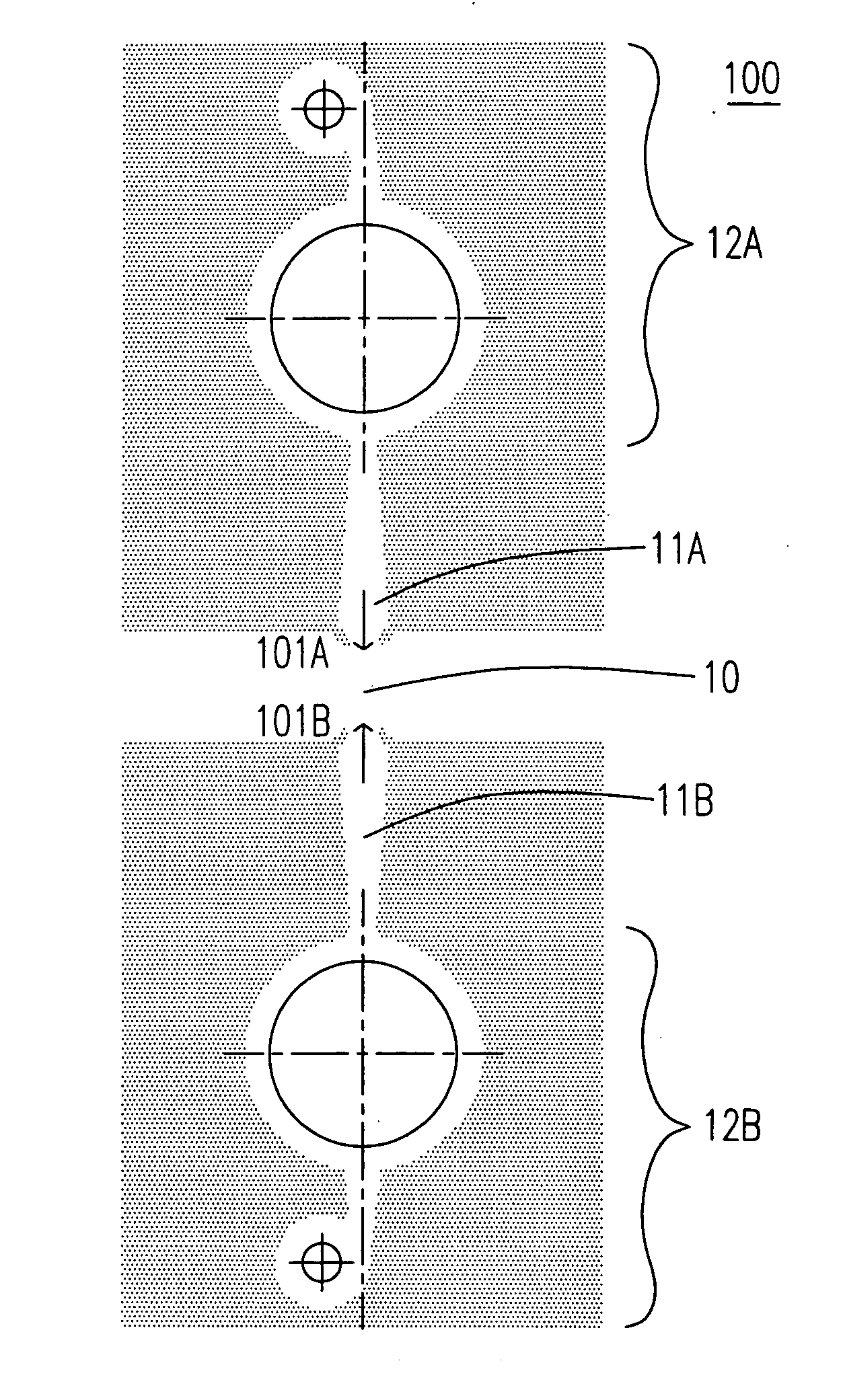
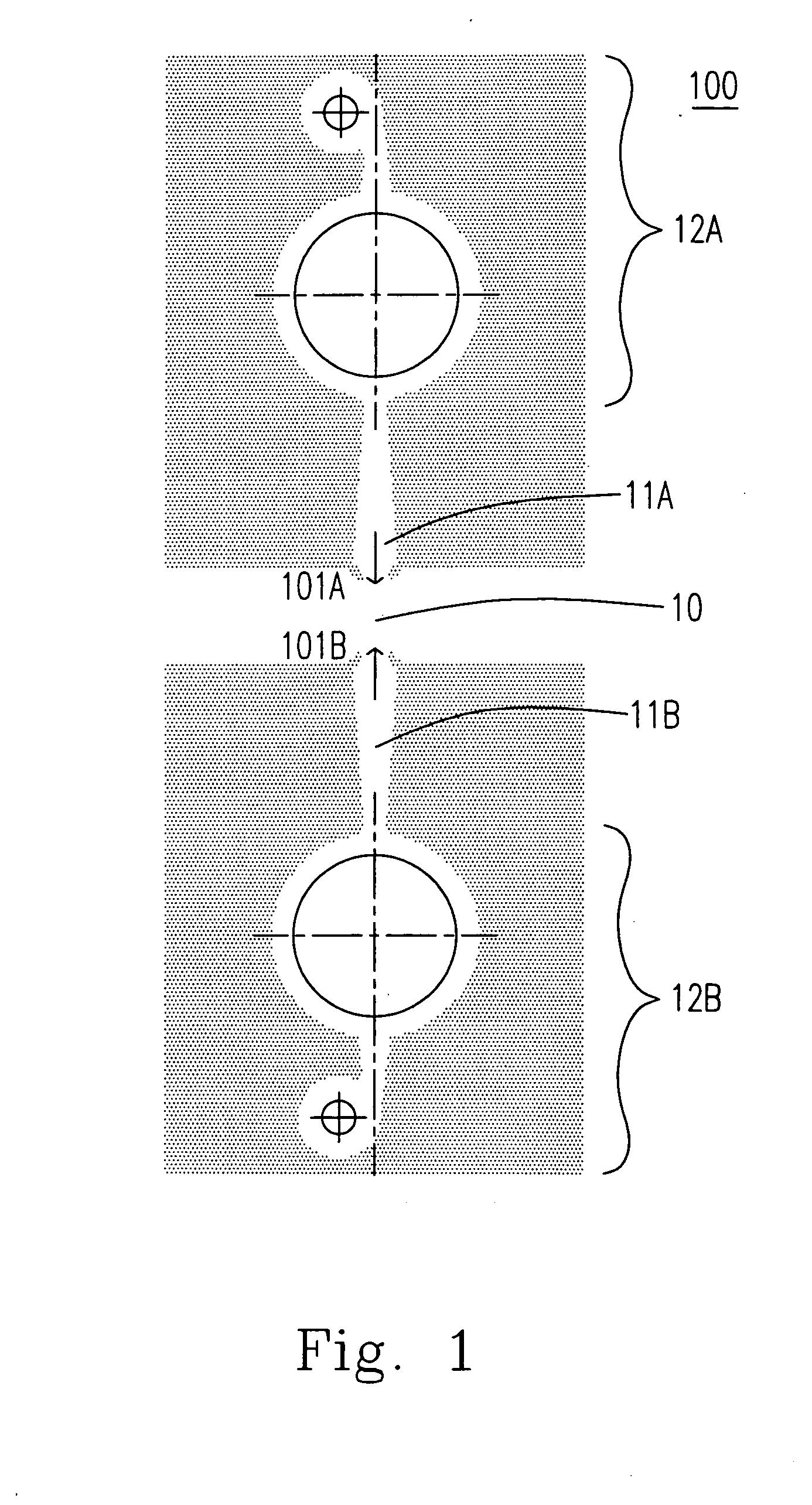
[0039] Please refer to FIG. 1, which shows a micromixer according to the first preferred embodiment of the present invention. The micromixer 100 includes a first and a second fluidic elements 11A, 11B, a mixing chamber 10 and a first and a second micropumps 12A, 12B. The first and the second micropumps are respectively configured at the inputs of the first and the second fluidic elements 11A, 11B. With the reciprocations of the first and the second micropumps 12A, 12B, a first and a second pulsation jets 101A, 101B are generated. The mixing chamber 10 is configured between the first and the second fluidic elements 11A, 11B. Dur...


PUM


Abstract

A micromixer used for microfluidic system is provided. The micromixer incorporates a pairs of reciprocating pumps and a pairs of fluidic element for mixing at least two fluids. With such a microfluid mixer, the at least two fluids are mixed when the reciprocating pumps are in their forward strokes by means of the impingement of two pulsation flows. The two fluids are also mixed when the reciprocating pumps are in their backward strokes by means of the generation of the vortexes, and the two fluids are also mixed by means of mass diffusion via a purposeful like-lamella-structure.

Description

FIELD OF THE INVENTION [0001] The present invention relates to a mixing apparatus, and more specifically to a mixing apparatus used for microfluidic system. BACKGROUND OF THE INVENTION [0002] A mixer is an apparatus for mixing at least two different fluids. With the operation of the mixer, at least two different fluids can be mixed rapidly and evenly. However, for different applications, it may be necessary to design a purposeful mixer for satisfying the specific demand, such as, precise mixing time, precise mixing temperature, precise mixing position. And this is especially important in the field of the microfluidic system. As the rapid development of the microfluidic system, it is still desirable to provide a micromixer with simple structures, low power consumptions and high mixing efficiency for the microfluidic system. [0003] In general, the microfluidic system means that the hydraulic diameters of the flow channels thereof are smaller than 500 μm, and even to the order of 101 μ...

Claims


Application Information

Patent Timeline
IPC IPC(8): F15C1/20
CPCB01F5/0256B01F11/0071B01F13/0072B01F13/0059B01F13/0066B01F11/0074Y10T137/2174B01F25/23B01F31/651B01F31/65B01F33/3022B01F33/3012B01F33/30
Inventor WANG, AN-BANGTRAVNICEK, ZDENEKLEE, CHUN-HSIENWANG, YI-HUAHSU, MING-CHANGLEE, CHIH-KUNGFEDORCHENKO, ALEXANDER I.
Owner NAT TAIWAN UNIV
Why Eureka
Try Eureka