Strong turbulent flow generating device for rapidly sorting micro-fine particles

A generating device and fine particle technology, applied in flotation, solid separation, etc., can solve the problems of increasing operating costs and increasing energy consumption, and achieve the effects of low cost, increased turbulence intensity, and simple structure

Active Publication Date: 2020-02-11
CHINA UNIV OF MINING & TECH
View PDF8 Cites 2 Cited by
  • Summary
  • Abstract
  • Description
  • Claims
  • Application Information

AI Technical Summary

Problems solved by technology

Generally, the method to increase the turbulence intensity in the flotation device is to increase the external energy input, such as increasing the impeller rotation speed in the flotation machine, etc., but this method increases more energy consumption while strengthening the recovery of fine particles, and improves running cost

Method used


Image

  • Strong turbulent flow generating device for rapidly sorting micro-fine particles
  • Strong turbulent flow generating device for rapidly sorting micro-fine particles
  • Strong turbulent flow generating device for rapidly sorting micro-fine particles

Examples


Embodiment 1

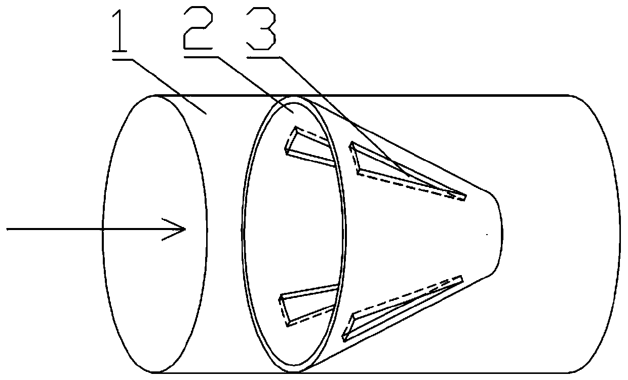
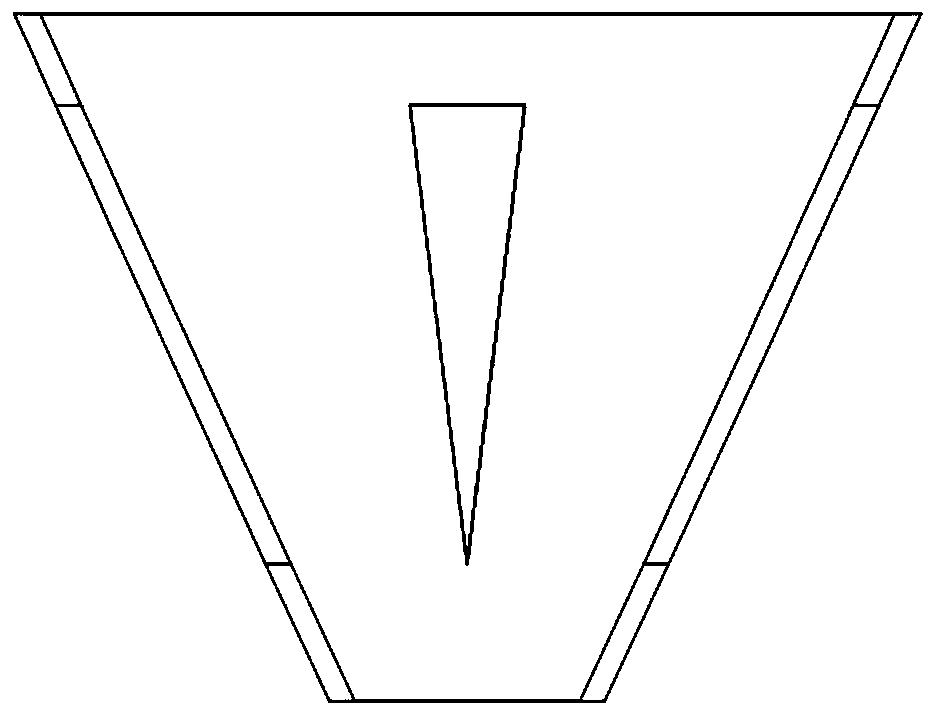
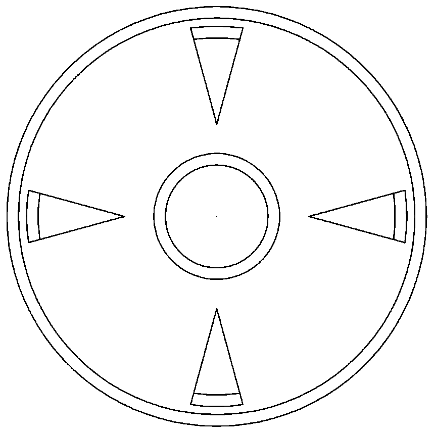
[0021] A strong turbulent flow generating device suitable for rapid separation of fine particles, comprising a cylindrical pipe flow section 1, and several conical rings 2 arranged in the pipe flow section, wherein each conical ring 2 is arranged along the pipe flow The axial direction of the section is evenly arranged, and the interval between the conical rings 2 is 15mm. The installation direction of the conical rings 2 in the pipe flow section 1 is set so that the slurry flows from the bottom surface to the top surface; the outer surface of the conical ring bottom surface Diameter D 1 The same as the inner diameter of pipe flow section 1, the outer diameter D of the top surface of the conical ring 2 and the outer diameter of the bottom surface D 1 The ratio is 0.4, and the angle between the outer wall of the conical ring and the inner wall of the pipe flow section is 25°. In order to avoid energy loss, there is no gap between the edge of the bottom surface of the conical r...

Embodiment 2

[0023] Such as Figure 1 to Figure 3 As shown, a strong turbulence generating device suitable for rapid separation of fine particles includes a cylindrical pipe flow section 1, and also includes several conical rings 2 arranged in the pipe flow section, wherein each conical ring 2 along the The axial direction of the pipe flow section is evenly arranged, and the interval between the conical rings 2 is 20mm. The installation direction of the conical rings 2 in the pipe flow section 1 is set so that the slurry flows from the bottom surface to the top surface; the conical rings The outer diameter of the bottom surface D 1 The same as the inner diameter of pipe flow section 1, the outer diameter D of the top surface of the conical ring 2 and the outer diameter of the bottom surface D 1 The ratio is 0.6, and the angle between the outer wall of the conical ring and the inner wall of the pipe flow section is 30°. In order to avoid energy loss, there is no gap between the edge of th...

Embodiment 3

[0025] A strong turbulent flow generating device suitable for rapid separation of fine particles, comprising a cylindrical pipe flow section 1, and several conical rings 2 arranged in the pipe flow section, wherein each conical ring 2 is arranged along the pipe flow The axial direction of the section is evenly arranged, and the interval between the conical rings 2 is 25mm. The installation direction of the conical rings 2 in the pipe flow section 1 is set so that the slurry flows from the bottom surface to the top surface; the outer surface of the conical ring bottom surface Diameter D 1 The same as the inner diameter of pipe flow section 1, the outer diameter D of the top surface of the conical ring 2 and the outer diameter of the bottom surface D 1 The ratio is 0.6, and the angle between the outer wall of the conical ring and the inner wall of the pipe flow section is 45°. In order to avoid energy loss, there is no gap between the edge of the bottom surface of the conical r...


PUM

PropertyMeasurementUnit
Granularityaaaaaaaaaa

Abstract

The invention discloses a strong turbulent flow generating device for rapidly sorting micro-fine particles. The device comprises a cylindrical pipe flow section and a plurality of conical rings arranged in the pipe flow section, wherein the conical rings are uniformly distributed in the axial direction of the pipe flow section, ore pulp flows from the bottom surface to the top surface by arrangingthe installation direction of the conical rings in the pipe flow section, the outer diameter D1 of the bottom surface of the conical ring is the same as the inner diameter of the pipe flow section, aratio of the outer diameter D2 of the top surface of the conical ring to the outer diameter D1 of the bottom surface of the conical ring is 0.3-0.8, the included angle between the outer side wall ofthe conical ring and the inner wall of the pipe flow section is 15-45 DEG, and a plurality of water through holes are uniformly formed in the outer side wall of the conical ring. According to the invention, the turbulent flow intensity can be improved without additional increase of energy consumption, the flotation granularity lower limit is reduced, and the recovery rate of micro-fine particles is increased.

Description

technical field [0001] The invention relates to a pipe flow device, in particular to a strong turbulent flow generating device suitable for rapid separation of fine particles, and belongs to the technical field of mineral processing equipment. Background technique [0002] The generation of fine-grained minerals is mainly due to the fact that the distribution of useful minerals is too small and must be finely ground, or due to over-grinding of coarse-grained minerals. With the reduction of ore particle size, the mass of ore particles decreases and the specific surface area increases. In conventional flotation, the probability of collision of ore particles is reduced, the specificity of reagents is poor, and mechanical inclusions are caused, which ultimately leads to the concentration and recovery of concentrates. rate drops. At the same time, due to the decrease of the particle size, the interference of the surface electrical properties of the fine particles on its flotatio...

Claims


Application Information

Patent Timeline
IPC IPC(8): B03D1/16
CPCB03D1/16Y02P70/10
Inventor 王利军郑恺昕李晓恒闫小康张海军曹亦俊
Owner CHINA UNIV OF MINING & TECH
Why Eureka
Try Eureka