Process for transferring coatings onto a surface of a lens substrate with most precise optical quality

Inactive Publication Date: 2006-10-05
ESSILOR INT CIE GEN DOPTIQUE
View PDF19 Cites 57 Cited by
  • Summary
  • Abstract
  • Description
  • Claims
  • Application Information

AI Technical Summary

Benefits of technology

[0016] Therefore, one object of the invention is to provide a process or method for transferring at least one coating from a carrier onto a geometrically defined su

Problems solved by technology

The process requires to precisely dropping the liquid adhesive composition, either too much or too less of the liquid adhesive needs to be avoided, which renders the process more complicated and less cost effective.
Furthermore, this process may cause optical distortions when the liquid adhesive composition is not spread out very evenly on the lens curved surface.
In

Method used


Image

  • Process for transferring coatings onto a surface of a lens substrate with most precise optical quality
  • Process for transferring coatings onto a surface of a lens substrate with most precise optical quality
  • Process for transferring coatings onto a surface of a lens substrate with most precise optical quality

Examples


example 1

[0188] One uses the HMC carrier described above i.e. the PC carrier with the HMC coating comprising an impact resistant primer adhesive coating composition comprising a HMA polyurethane latex material (W-234, from Baxenden). This HMA latex becomes tacky when heated above 60° C. The tacky behavior can be repeated with heating and cooling.

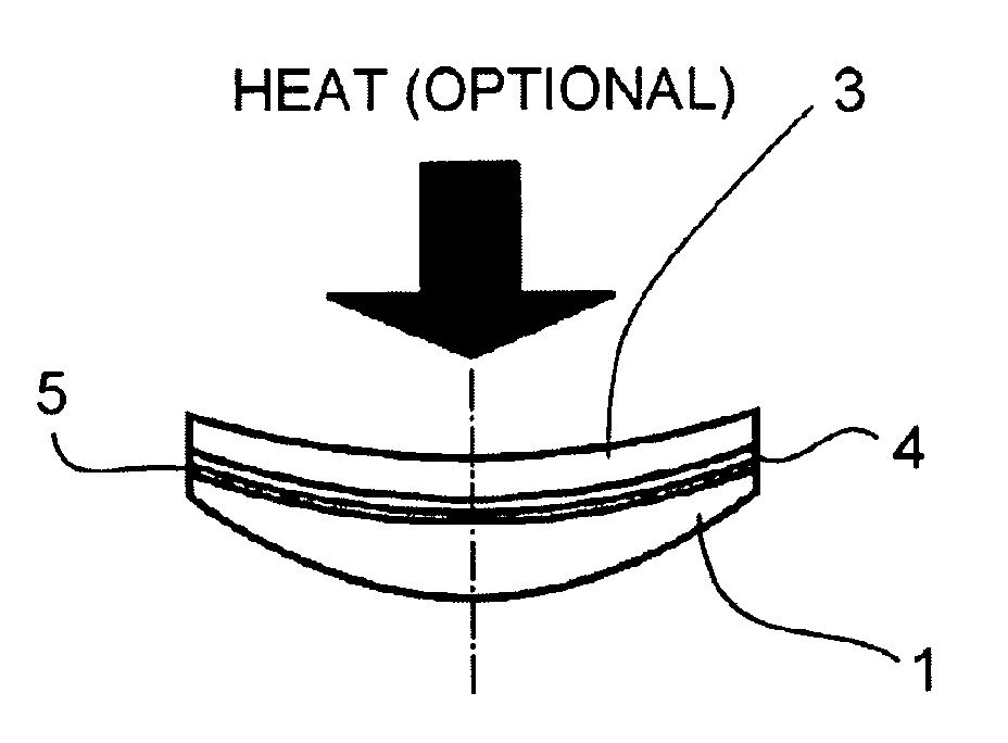
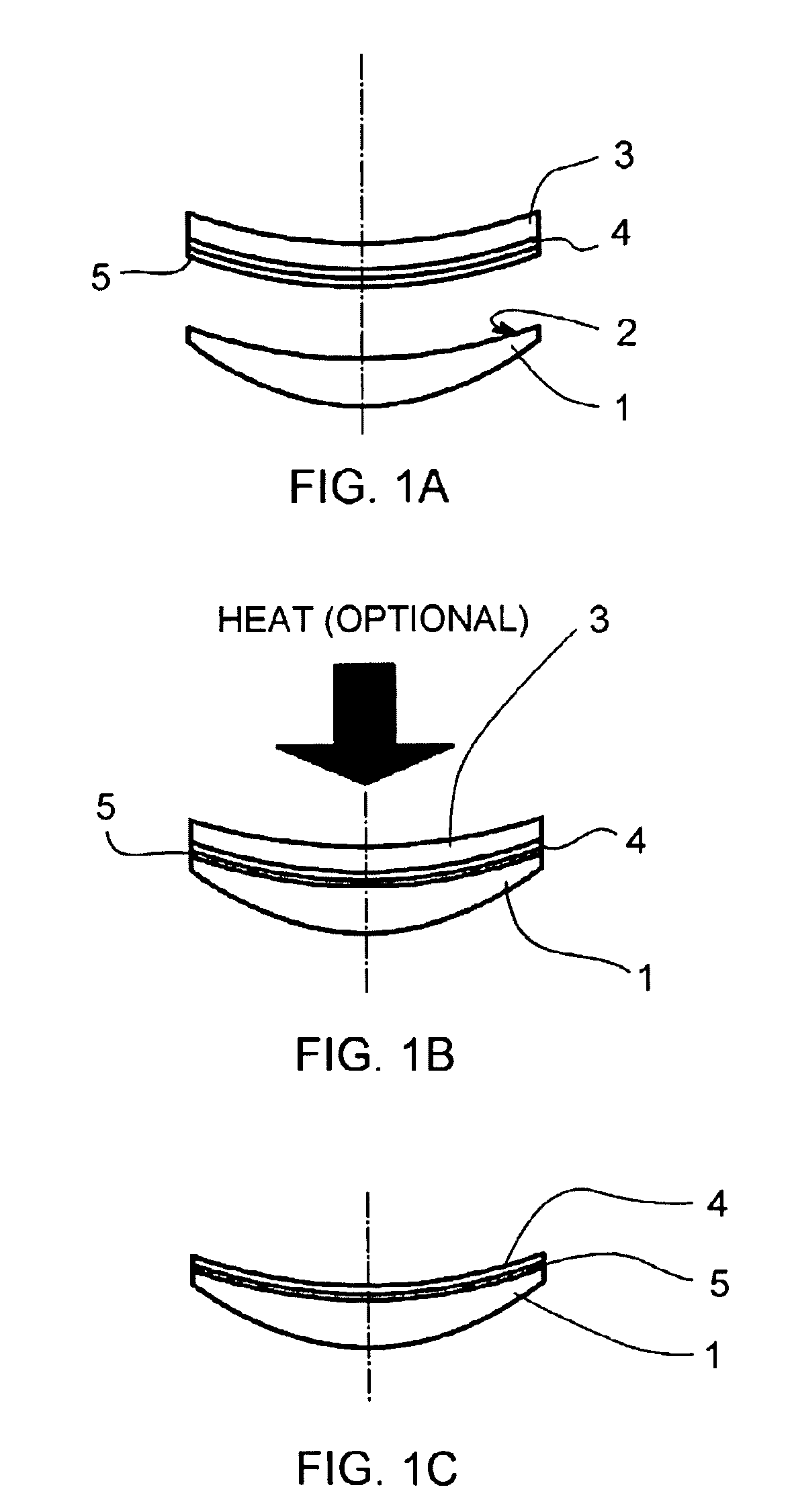
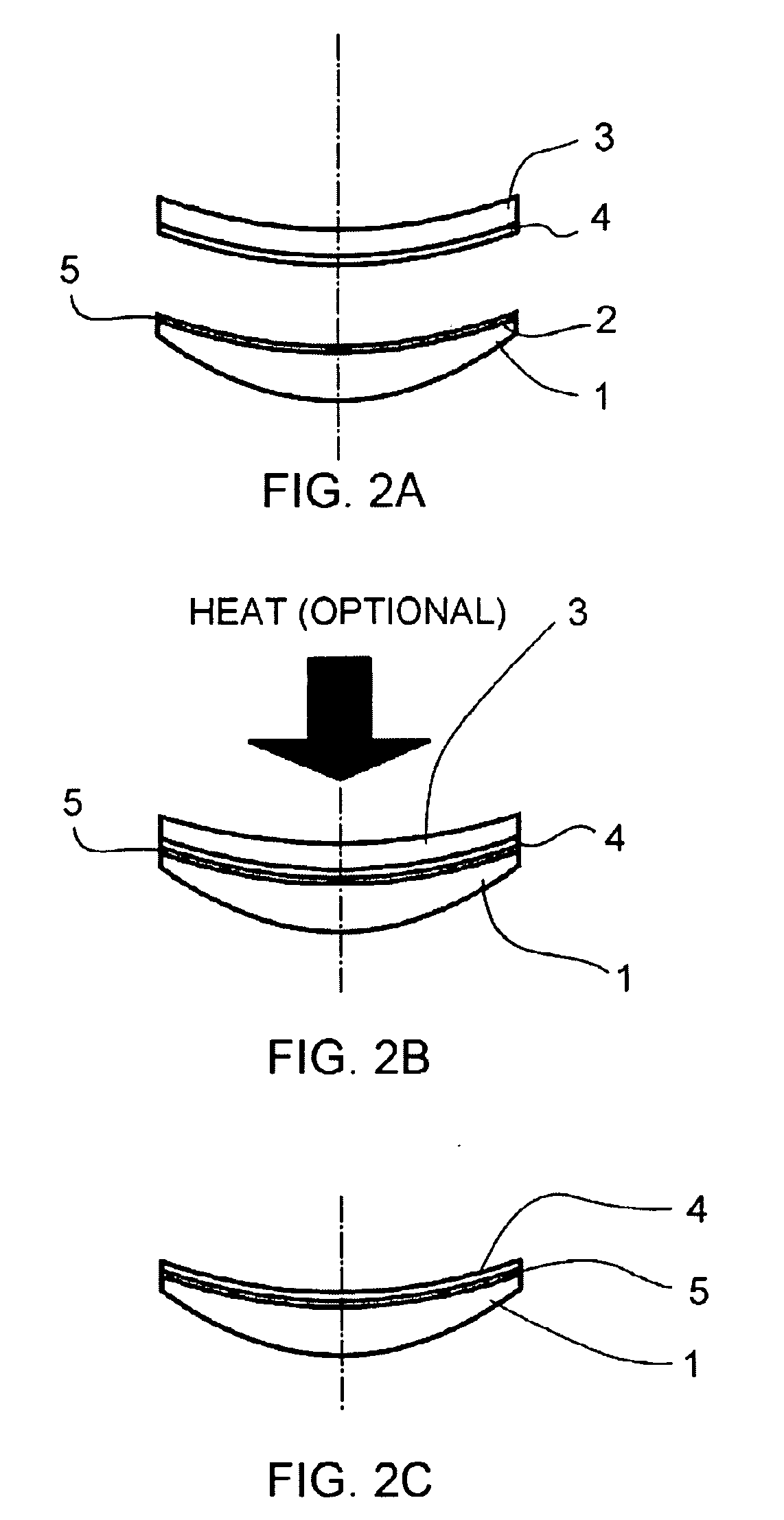
[0189] Then the HMC coating on the carrier was applied at room temperature to the back surface of a polycarbonate lens (−2.00, spherical, back curve 5.0) in the manner described in connection with FIGS. 1A to 1C: after applying an external air membrane pressure (12 psi-0.83 bar), the assembly of coated carrier and lens was heated at 110° C. for 20 minutes in air oven under the same pressure. Then it was cooled down and the carrier was removed with the HMC layer transferred to the lens surface. The transferred coating layer has very good adhesion on lens surface with a dry adhesion score of 0. There is no AR cracking during this transfer. The obtaine...

example 2

[0194] Same procedure as example 1, except a UV cross-linkable PSA formulation was used. PSA # US02008, Rahn Inc. was diluted in MEK (30 / 70 w / w) and spin-coated onto an HMC carrier (5.80 base). The resulting layer was then exposed to UV radiation for 30 seconds in an inert atmosphere. After exposure, the layer was dry, yet tacky to the touch. The HMC coating on the carrier was then transferred to the back surface of a polycarbonate lens (−2.00 D, back curve 5.0) in the manner described in connection with FIGS. 1A to 1C. An external air pressure (14 psi-0.98 bar) was applied for 30 seconds to the carrier / lens assembly, without UV or heat. After releasing the pressure, the carrier was removed from the back of the lens, with the coating stack and PSA layer remaining on the lens.

example 3

[0195] 2.1 g of Escorez 5380 resin from Exxon Mobil and 0.9 g of Vector 4100 block copolymer were added to 20 g of toluene and stirred until both had completely dissolved. This was the starting PSA solution and it contained 13% solids. Then it was prepared by diluting 5 g of starting solution with 5 g of toluene, resulting in a solution with 6.5% solids to get a final PSA solution. After that, it was spin coated onto the convex surface of a 5.8 base HMC pre-coated carrier at the following spin coating conditions:

Spin Coating Parameters

Slow speed: 500 rpm for 2 seconds

Fast speed: 200 rpm for 5 seconds

[0196] After PSA coating of the PSA layer, the carrier was allowed to air dry until the odor of toluene was no longer detectable. The convex side of the carrier was then placed onto the concave side of a −2.00 D polycarbonate lens with the back curve of 5.0 base, and subjected to the BST lamination process using the same procedure as example 1 except that the applied pressure is 1...


PUM

PropertyMeasurementUnit
Temperatureaaaaaaaaaa
Thicknessaaaaaaaaaa
Thicknessaaaaaaaaaa

Abstract

The present invention relates to a process for transferring at least one coating onto at least one geometrically defined surface of a lens substrate.

Description

BACKGROUND OF THE INVENTION [0001] 1. Field of the Invention [0002] The present invention relates to an improved process or method for transferring at least one coating onto at least one geometrically defined surface of a lens substrate, which can be implemented in a short period of time without any risk of deformation of the lens substrate, which avoids the use of a liquid curable adhesive composition for adhesion of the coating to the lens substrate and results in the coating adhering to the lens substrate through an adhesive layer of uniform thickness. [0003] 2. Description of Related Art [0004] It is a common practice in the art to coat at least one main surface of a lens substrate, such as an ophthalmic lens or lens blank, with several coatings for imparting to the finished lens additional or improved optical or mechanical properties. These coatings are designated in general as functional coatings. [0005] Thus, it is usual practice to coat at least one main surface of a lens su...

Claims


Application Information

Patent Timeline
IPC IPC(8): B32B37/00B32B37/10B32B37/12
CPCB29D11/0073
Inventor BEGON, CEDRICJIANG, PEIQIROOS, ALEXANDRAWEBER, STEVEN
Owner ESSILOR INT CIE GEN DOPTIQUE
Why Eureka
Try Eureka