
Automatic shoe clearance adjustment apparatus

a technology adjustment apparatus, which is applied in the direction of fluid actuated drum brakes, axially engaging brakes, braking elements, etc., can solve the problems of excessive complexity of automatic shoe clearance adjustment apparatus, unstable shoe clearance adjustment operation, and reduced component cost, so as to reduce the number of components needed, reduce the manufacturing cost of driving components, and reduce the effect of parts cos

Inactive Publication Date: 2006-10-05
NISSHINBO IND INC
View PDF3 Cites 12 Cited by
  • Summary
  • Abstract
  • Description
  • Claims
  • Application Information

AI Technical Summary

Benefits of technology

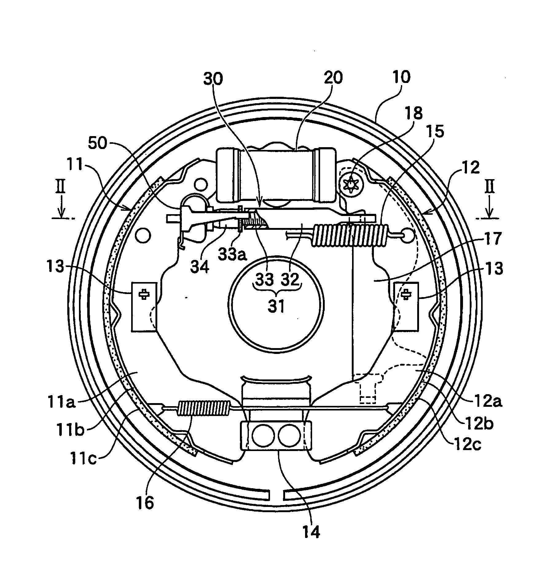
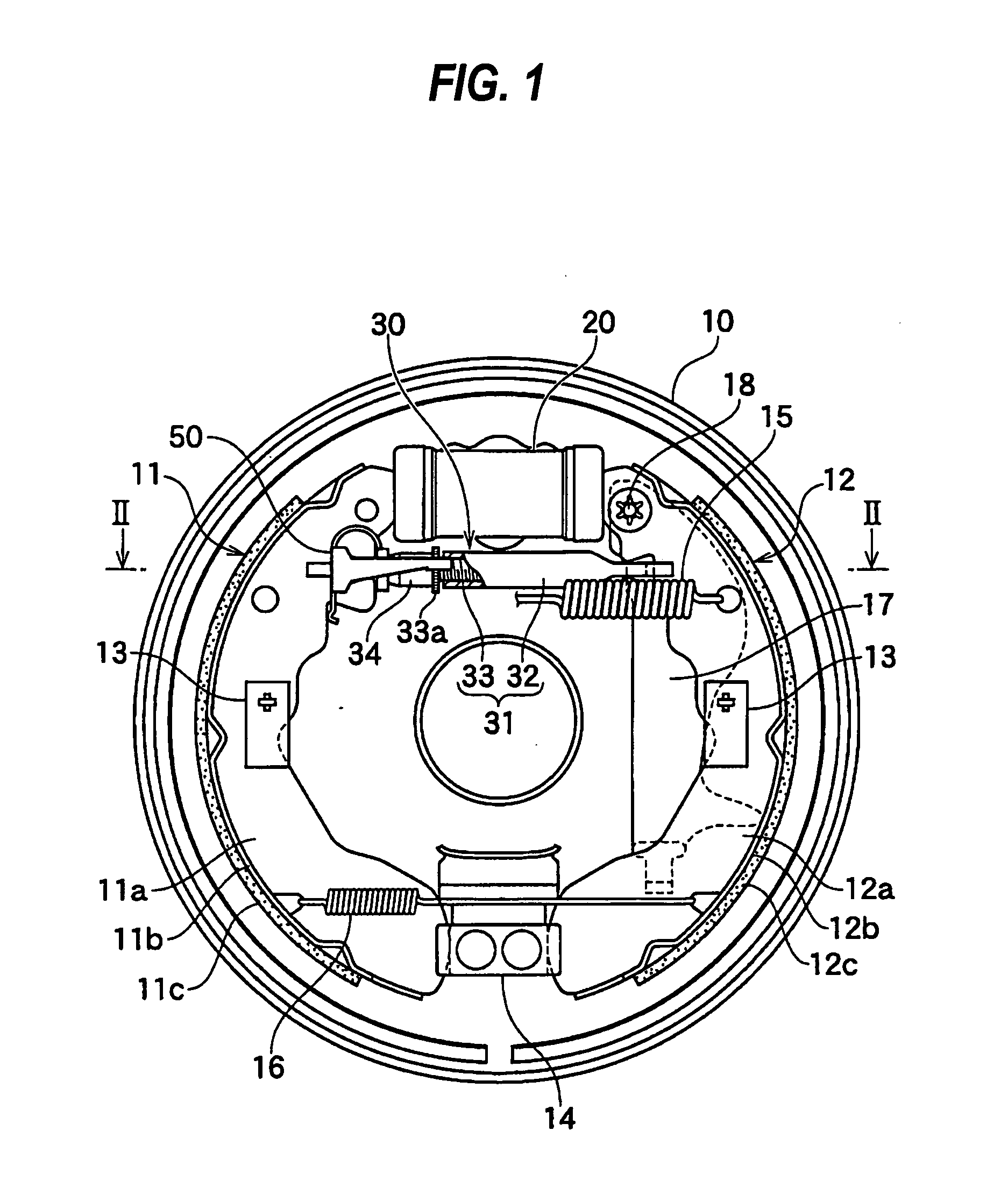
[0008] This invention is to provide lower cost with less complexity and further to provide a stable shoe clearance adjustment operation mainly by fixing a proximal portion of the driving member to the strut, resiliently abutting the operating portion extendedly formed from the proximal portion against the brake shoe between the brake shoe and the strut, and engaging a pawl end of an arm extending toward adjustment teeth of the strut from the operating portion with the adjustment teeth.
[0015] The automatic shoe clearance adjustment apparatus of this invention has the following advantages.
[0016]<1> The driving member can be made from a piece of plate spring, which significantly reduces the number of components necessary to constitute the driving member and also reduces the manufacturing cost of the driving member, which reduces the parts cost of the automatic shoe clearance adjustment apparatus. <2> The driving member can be fixed to the strut by the fitting means, which reduces the assembling cost. <3> The driving member can be stably fixed to an axial line of the strut, which creates smooth operation of the driving member and gives stable shoe clearance adjustment operation. <4> This invention is applicable to various types of struts, which gives a wide range of industrial applicability.

Problems solved by technology

Accordingly, the shoe clearance adjustment operation became unstable.
Problems of the conventional technology to be resolved by this invention are that the conventional technology involves a large number of components; the automatic shoe clearance adjustment apparatus is excessively complex; and the biasing force applied to the nut (rotating member) makes the shoe clearance adjustment operation unstable.

Method used


Image

  • Automatic shoe clearance adjustment apparatus
  • Automatic shoe clearance adjustment apparatus
  • Automatic shoe clearance adjustment apparatus

Examples


second embodiment

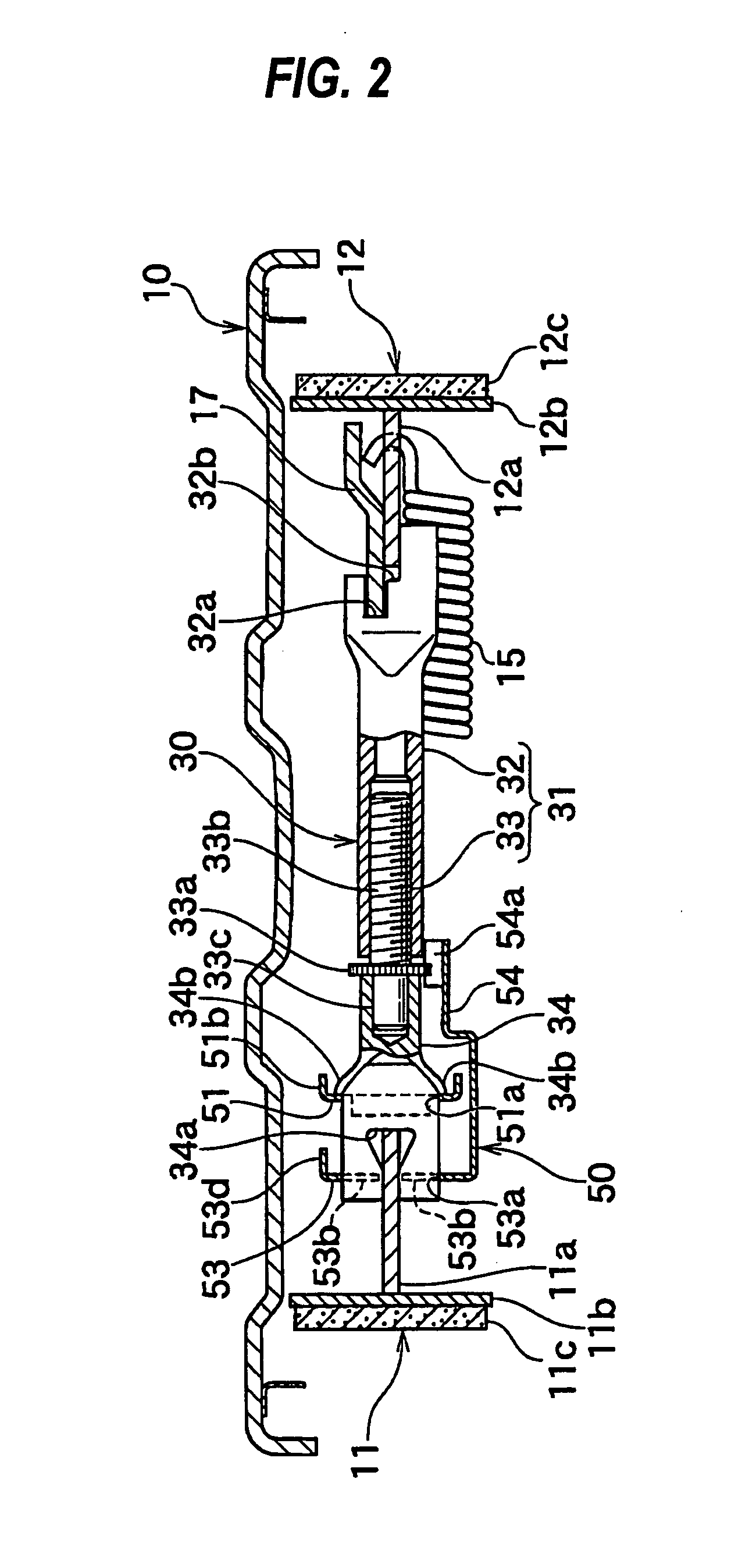
[0061] The automatic shoe clearance adjustment apparatus according to a second embodiment as shown in FIGS. 5-7 is comprised of a strut 30 having a nut 32 with adjustment teeth 32c on the peripheral surface thereof as a component, and a driving member 50 fixed on a screw-engaging unit 31 of the strut 30 by a rivet 55. The detailed structure thereof will be explained next.

Strut

[0062] The strut 30 as shown in FIG. 5 is comprised of the screw-engaging unit 31 having a nut 32 and a bolt 33 screwed therebetween and a fitting member 34 rotatably fitting to the screw-engaging unit 31. In this embodiment, the bolt 33 engages with the shoe web 11a of the first brake shoe 11, and the fitting member 34 engages with the brake lever 17 and the shoe web 12a of the second brake shoe 12.

[0063] The screw-stem 33b of a right side of the bolt 33 rotatably and slidably fits in a bore of the fitting member 34, and the end surface of the fitting member 34 abuts against the nut 32, thereby positioning...

third embodiment

[0074] The automatic shoe clearance adjustment apparatus according to a third embodiment as shown in FIGS. 8-11 is based on the strut 30 identical to the above-described first embodiment and has a driving member 50 with different layout and operation from the first embodiment. The structure and the functions of the strut 30 in this third embodiment are identical to that of the first embodiment and therefore the explanation thereof is omitted here.

Driving Member

[0075]FIG. 9 shows an overall perspective view of the driving member 50 and FIGS. 8 and 10 show the driving member 50 being assembled between the strut 30 and the first brake shoe 11.

[0076] The driving member 50 is comprised of an arc portion 52, a proximal portion 51 lineally extending from one side surface at one end side of the arc portion 52 and being fixed to the fitting member 34 of the strut 30, an operating portion 53 lineally extending from the other side surface at the other end side of the arc portion 52 so as t...

fourth embodiment

[0087] The automatic shoe clearance adjustment apparatus according to a fourth embodiment as shown in FIGS. 12-14 is comprised of a strut 30 having a cylindrical nut 32 with adjustment teeth 32c on the peripheral surface thereof as a component and a driving member 50 attached to a fitting member 34 of the strut 30 and automatically extends the entire length of the strut 30 by the resilient force for pressing an arc portion 52. The detailed structure thereof will be explained below.

Strut

[0088] The strut 30 as shown in FIG. 12 is comprised of the screw-engaging unit 31 having the bolt 33 and the nut 32 screwed therebetween and the fitting member 34 rotatably fitting to the screw-engaging unit 31. In this embodiment, the fitting member 34 engages with the shoe web 11a of the first brake shoe 11 and the bolt 33 of the screw-engaging unit 31 engages with the shoe web 12a of the second brake shoe 12.

Driving Member

[0089]FIG. 13 shows an overall perspective view of the driving member ...


PUM


Abstract

To reduce the number of components of the automatic shoe clearance adjustment apparatus and to improve the ease of assembly of the same, the proximal portion of the driving member is fixed on the strut. The operating portion and the arm of the driving member are integrally formed therewith is placed between the brake shoe and the strut. The operating portion together with the arm of the driving member are moved (rotated) so as to follow the movement of the brake shoe by utilizing the resilient force of the driving member, and the pawl at the end of the arm drives the adjustment teeth of the strut to extend the entire length of the strut.

Description

FIELD OF THE INVENTION [0001] This invention relates to an automatic shoe clearance adjustment apparatus for a drum brake device. BACKGROUND OF THE INVENTION [0002] An example of this type of automatic shoe clearance adjustment apparatus is described in Japanese Provisional Patent Publication No. 58-77931 and European Provisional Patent Publication No. 0077726 (Related prior art 1). The automatic shoe clearance adjustment apparatus is comprised of a strut extended between a pair of brake shoes and a driving member to make a ratchet engagement with adjustment teeth integrated with the strut and adjusts the shoe-to-drum clearance automatically by extending an entire length of the strut when a shoe-to-drum clearance increases because a brake lining is worn out. [0003] The strut disclosed in the related prior art 1, as shown in FIGS. 19 and 20, has a screw-engaging unit fitting a bolt 61 to a nut 62 having adjustment teeth 62a and a socket 63 slidably fitting on a screw-stem of the bolt...

Claims


Application Information

Patent Timeline
Patent Type & Authority Applications(United States)
IPC IPC(8): F16D55/02
CPCF16D51/20F16D65/563F16D51/24
Inventor TANIGUCHI, YUUSUKEARAI, NOBUHISA
Owner NISSHINBO IND INC
Learn More