Rocker-arm actuator for a segmented mirror

a rocker-arm actuator and mirror technology, applied in the field of microelectromechanical systems, can solve the problems of reducing the fill factor, difficult or even impossible to meet, etc., and achieve the effect of reducing the potential physical interference and large fill factor

Inactive Publication Date: 2006-10-05
LUCENT TECH INC
View PDF17 Cites 12 Cited by
  • Summary
  • Abstract
  • Description
  • Claims
  • Application Information

AI Technical Summary

Benefits of technology

[0007] Problems in the prior art are addressed, in accordance with the principles of the present invention, by a MEMS device having a movable plate supported on a substrate by a support structure that is hidden under the plate and yet which can be implemented to enable rotation of the plate with respect to the substrate about a rotation axis lying at the plate surface. Advantageously, the support structure does not take up any area within the plane of the plate, while enabling rotation of the plate, during which the plate does not substantially move sideways. Further advantageously, the latter property reduces potential physical interference between neighboring plates in an arrayed MEMS device and enables implementation of a segmented mirror having relatively narrow gaps between adjacent segments and, thus, a relatively large fill factor, e.g., at least 98%.

Problems solved by technology

However, for many prior-art designs, these requirements are in direct conflict with each other and therefore difficult or even impossible to meet.
The latter, however, reduces the fill factor.

Method used


Image

  • Rocker-arm actuator for a segmented mirror
  • Rocker-arm actuator for a segmented mirror
  • Rocker-arm actuator for a segmented mirror

Examples


Embodiment Construction

[0018] Reference herein to “one embodiment” or “an embodiment” means that a particular feature, structure, or characteristic described in connection with the embodiment can be included in at least one embodiment of the invention. The appearances of the phrase “in one embodiment” in various places in the specification are not necessarily all referring to the same embodiment, nor are separate or alternative embodiments mutually exclusive of other embodiments.

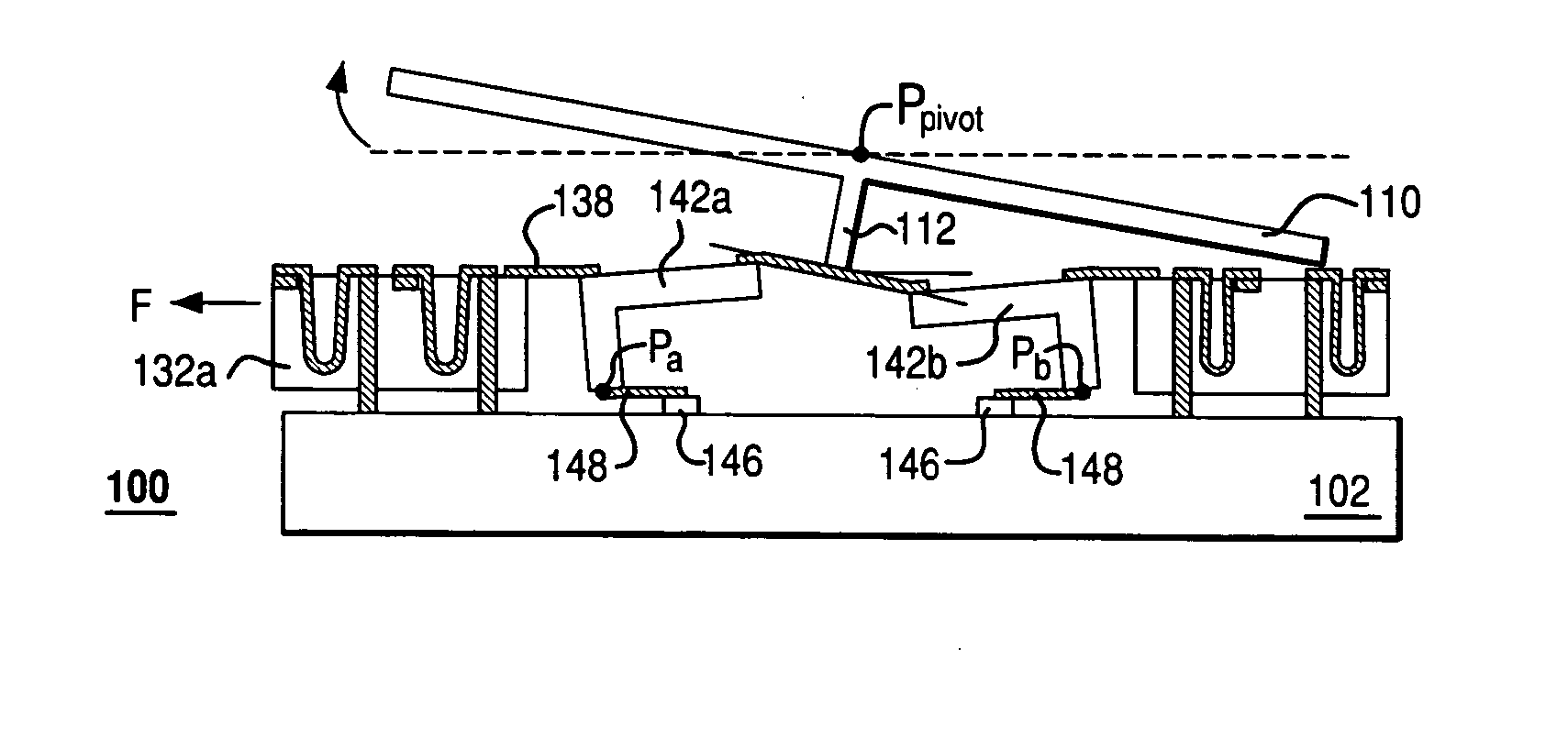
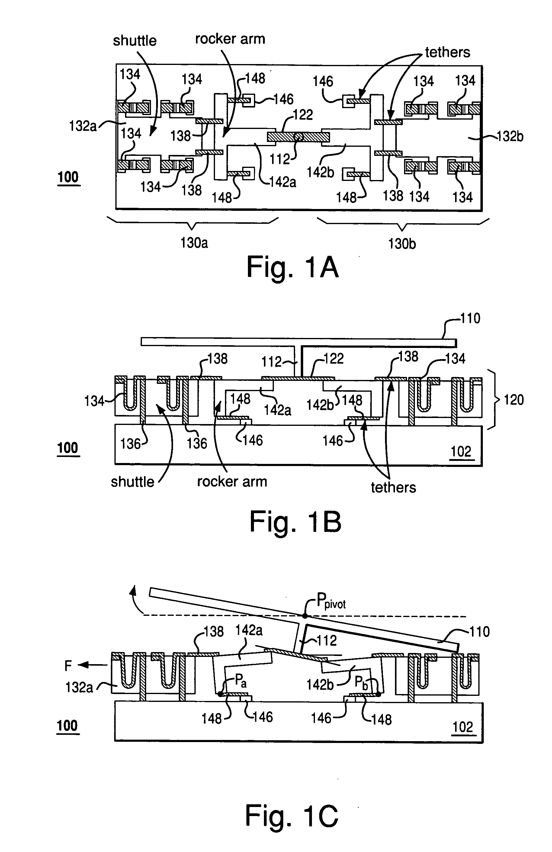
[0019] FIGS. 1A-C show top and side views of a MEMS device 100 according to one embodiment of the invention. More specifically, FIG. 1A shows a cutout top view of device 100, and FIGS. 1B-C show side views of the device with its movable plate 110 in two different rest positions. Movable plate 110 in device 100 is mounted on a motion actuator 120, which is supported on a substrate 102. In one embodiment, plate 110 has a reflective top surface and can serve as a segment of a segmented mirror. Actuator 120 has two actuator portions ...


PUM


Abstract

A MEMS device having a movable plate supported on a substrate by a support structure that is hidden under the plate and yet which can be implemented to enable rotation of the plate with respect to the substrate about a rotation axis lying at the plate surface. As a result, the support structure does not take up any area within the plane of the plate, while enabling rotation of the plate, during which the plate does not substantially move sideways. The latter property reduces potential physical interference between neighboring plates in an arrayed MEMS device and enables implementation of a segmented mirror having relatively narrow gaps between adjacent segments and, thus, a relatively large fill factor, e.g., at least 98%.

Description

BACKGROUND OF THE INVENTION [0001] 1. Field of the Invention [0002] The present invention relates to adaptive optics and spatial light modulators for optical maskless lithography (OML) and, more specifically, to micro-electromechanical systems (MEMS) for implementing adaptive optics and / or spatial light modulators. [0003] 2. Description of the Related Art [0004] Adaptive optics is a field of optics dedicated to the improvement of optical signals using information about signal distortions introduced by the environment in which the optical signals propagate. A representative example of an adaptive optical element is a deformable mirror driven by a wavefront sensor. An excellent introductory text on the subject is given in “Principles of Adaptive Optics” by R. K. Tyson, Academic Press, San Diego, 1991, the teachings of which are incorporated herein by reference. [0005] Optical maskless lithography (OML) is an emerging technology intended as a replacement for conventional mask-based lit...

Claims


Application Information

Patent Timeline
Patent Type & Authority Applications(United States)
IPC IPC(8): H02N1/00G02B26/08
CPCH02N1/008G02B26/0833
Inventor GREYWALL, DENNIS S.
Owner LUCENT TECH INC
Why Eureka
Try Eureka