

Power supply apparatus, and image forming apparatus having the same
a technology of power supply apparatus and image forming apparatus, which is applied in the direction of generator/motor, electrographic process, instruments, etc., can solve the problems of difficult to improve the output precision of high bias voltage, image quality may degrade, and it is difficult to take these measures by theoretical calculation. achieve the effect of suppressing interference and high image quality
- Summary
- Abstract
- Description
- Claims
- Application Information
AI Technical Summary
Benefits of technology
Problems solved by technology
Method used
Image

Examples
first embodiment
[0044] The first embodiment of the present invention will be described below with reference to the accompanying drawings. FIG. 2 is a view showing an image forming apparatus (to be referred to as a “color laser printer” hereinafter) having a high-voltage power supply apparatus 202 using a piezoelectric transformer. A color laser printer 401 comprises a deck 402 which stores print sheets 32, and a deck sheet presence / absence sensor 403 which detects the presence / absence of the print sheets 32 in the deck 402. The color laser printer 401 also comprises a pickup roller 404 which picks up the print sheet 32 from the deck 402, and a deck sheet feed roller 405 which conveys the print sheet 32 picked up by the pickup roller 404. The color laser printer 401 further comprises a retard roller 406 which is paired with the deck sheet feed roller 405 and prevents multi-feed of the print sheets 32.
[0045] A registration roller pair 407 which synchronously conveys the print sheet 32, and a pre-reg...
second embodiment
[0084] The first embodiment has described a method of driving piezoelectric transformers at different frequencies in order to preclude mutual interference between the piezoelectric transformers in a high-voltage power supply apparatus using a voltage doubler rectification circuit. The second embodiment will explain a high-voltage power supply apparatus using a piezoelectric transformer which does not require any voltage doubler rectification circuit when, for example, the output voltage is relatively low.
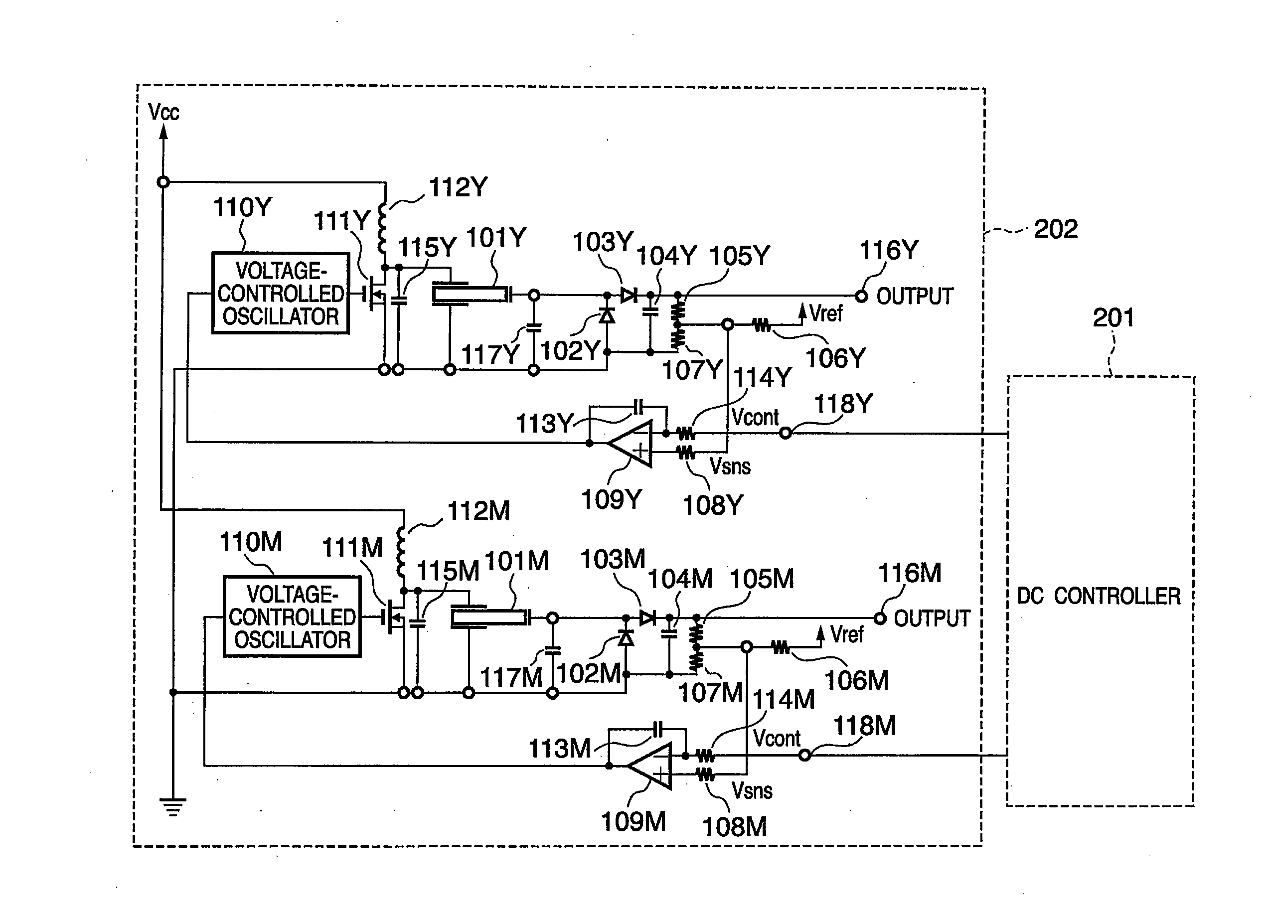
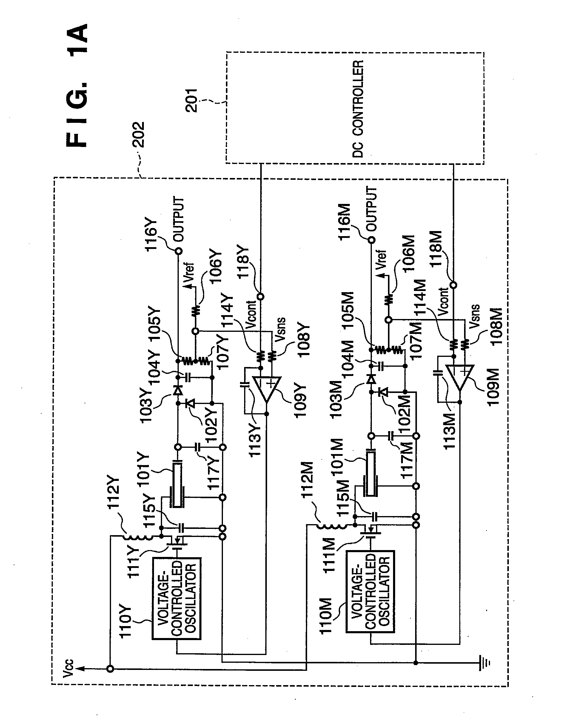
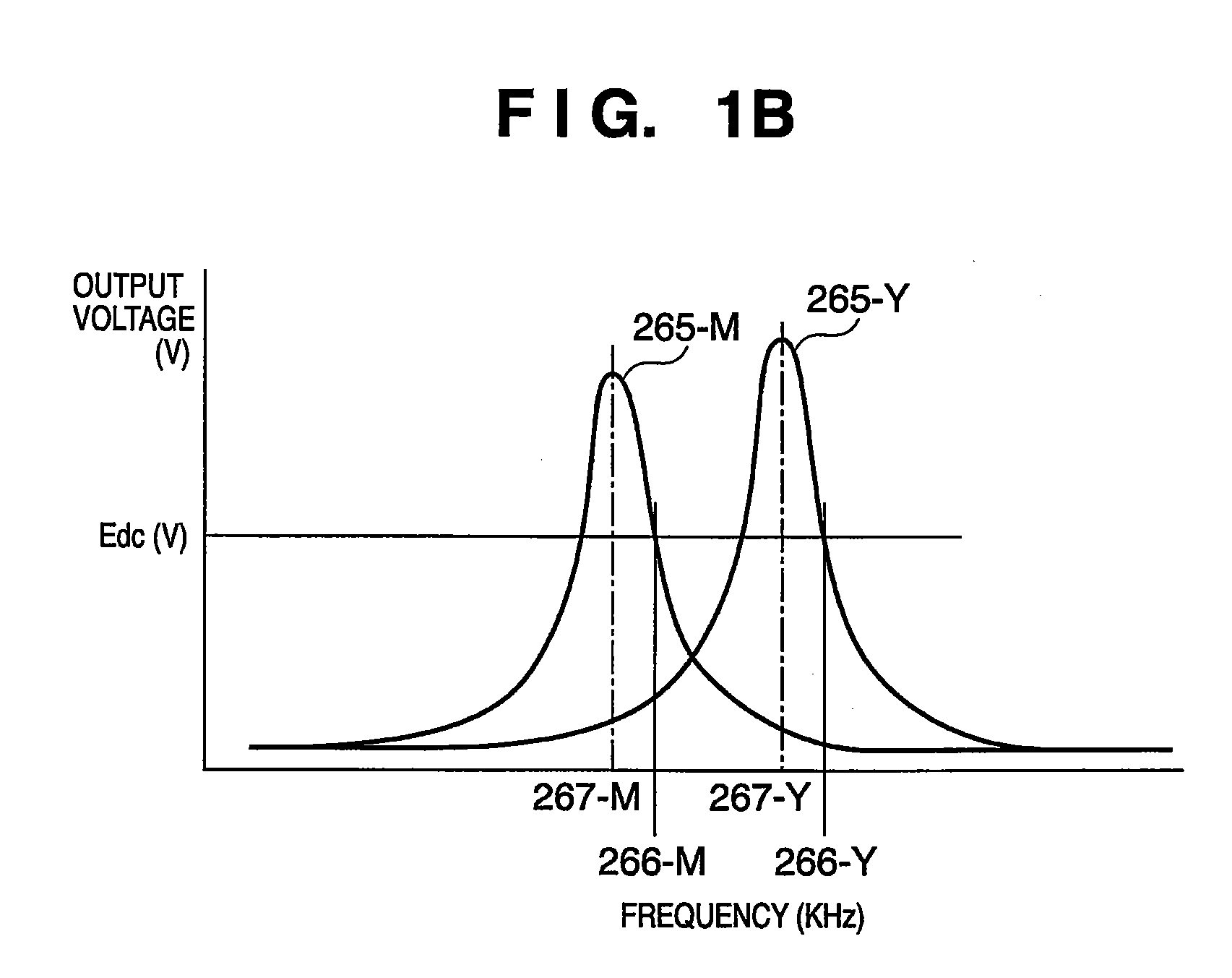
[0085]FIG. 4A is a circuit diagram showing the circuit arrangement of a transfer high-voltage power supply using a piezoelectric transformer according to the second embodiment. FIG. 4B is a graph showing the relationship (frequency characteristic) between the driving frequencies and output voltages of piezoelectric transformers 101Y and 101M of the high-voltage power supply when yellow (Y) and magenta (M) images are formed by the circuit arrangement (FIG. 4A). Note that a descripti...
third embodiment
[0097]FIG. 5A is a circuit diagram showing the circuit arrangement of a transfer high-voltage power supply using a piezoelectric transformer according to the third embodiment of the present invention. Note that a description of the same building components as those of the circuit arrangements described in the first and second embodiments will be omitted. The third embodiment is mainly different from the first and second embodiments in that the number of diodes (rectification elements) used which are connected between ground and the output terminal of a piezoelectric transformer 101 is changed in a high-voltage power supply apparatus using a voltage doubler rectification circuit.
[0098] In the circuit arrangement shown in FIG. 5A, high-voltage diodes 102Y, 102M, and 120M used in the rectification circuit generally have an electrostatic capacitance of 3 to 4 pF. The third embodiment positively utilizes the electrostatic capacitances of the diodes, and performs the same operation as th...
PUM
 Abstract
Description
Claims
Application Information