Maximizing efficiency of battery-powered LED drivers

a technology of led driver and efficiency, applied in the field of power management, can solve the problems of limited battery operation time, low relatively high power efficiency of boost regulator, so as to minimize low system cost. , the effect of minimizing the overall long-term total power dissipation

Active Publication Date: 2006-10-05
ANALOG DEVICES INC
View PDF2 Cites 31 Cited by
  • Summary
  • Abstract
  • Description
  • Claims
  • Application Information

AI Technical Summary

Benefits of technology

[0009] The present invention offers low cost solutions for powering multiple LEDs while minimizing overall long-term total power dissipation in battery-powered devices such as cellular telephones. Low system cost is attained using a charge pump (CP) that may be implemented to increase available voltage level. The present invention additionally provides methods and apparatus to overcome the inefficiency of charge pumps and enables improved efficiency of battery usage. Efficiency levels of 90-97% are attainable depending on external parameters such as LED voltage and rated battery voltage, and internal parameters such as voltage drops associated with control circuitry.
[0010] The present invention incorporates a charge pump, and a switch that bypasses the charge pump when battery output voltage is sufficient to directly drive an LED load. When battery voltage drops below a certain threshold level, the switch is typically opened and the charge pump operates to boost drive voltage. Additionally, other techniques may be combined to improve efficiency. For example, a multi-stage drive system can be implemented in which the battery voltage is initially PWM modulated to drive the LED load, then drives the LED load directly before the battery voltage drops below a threshold at which the charge pump is engaged.

Problems solved by technology

However, LEDs operate only when a sufficient voltage is available and illumination intensities are susceptible to variations in battery voltage levels.
A drawback of this approach lies in the relatively power efficiencies of boost regulators, which typically operate between 50% and 80% efficiency.
Systems that operate without boost regulators may benefit from greater efficiency when operational, but suffer from limited battery operational time.
The operational time of the battery is limited because in these systems, when voltage produced by the battery drops below a level required to turn on the display may become unreadable and the device unusable.
It should be apparent that in order to obtain an apparent intensity equal to a constant voltage driven LED, PWM suffers from the drawback that higher voltages and currents must be used, albeit for relatively short durations.
This requirement for higher voltages necessitates the use of a higher voltage battery or the addition of a relatively inefficient voltage booster.

Method used


Image

  • Maximizing efficiency of battery-powered LED drivers
  • Maximizing efficiency of battery-powered LED drivers
  • Maximizing efficiency of battery-powered LED drivers

Examples


Embodiment Construction

[0018] Embodiments of the present invention will now be described in detail with reference to the drawings, which are provided as illustrative examples so as to enable those skilled in the art to practice the invention. Notably, the figures and examples below are not meant to limit the scope of the present invention. Where certain elements of these embodiments can be partially or fully implemented using known components, only those portions of such known components that are necessary for an understanding of the present invention will be described, and detailed descriptions of other portions of such known components will be omitted so as not to obscure the invention. Further, the present invention encompasses present and future known equivalents to the components referred to herein by way of illustration.

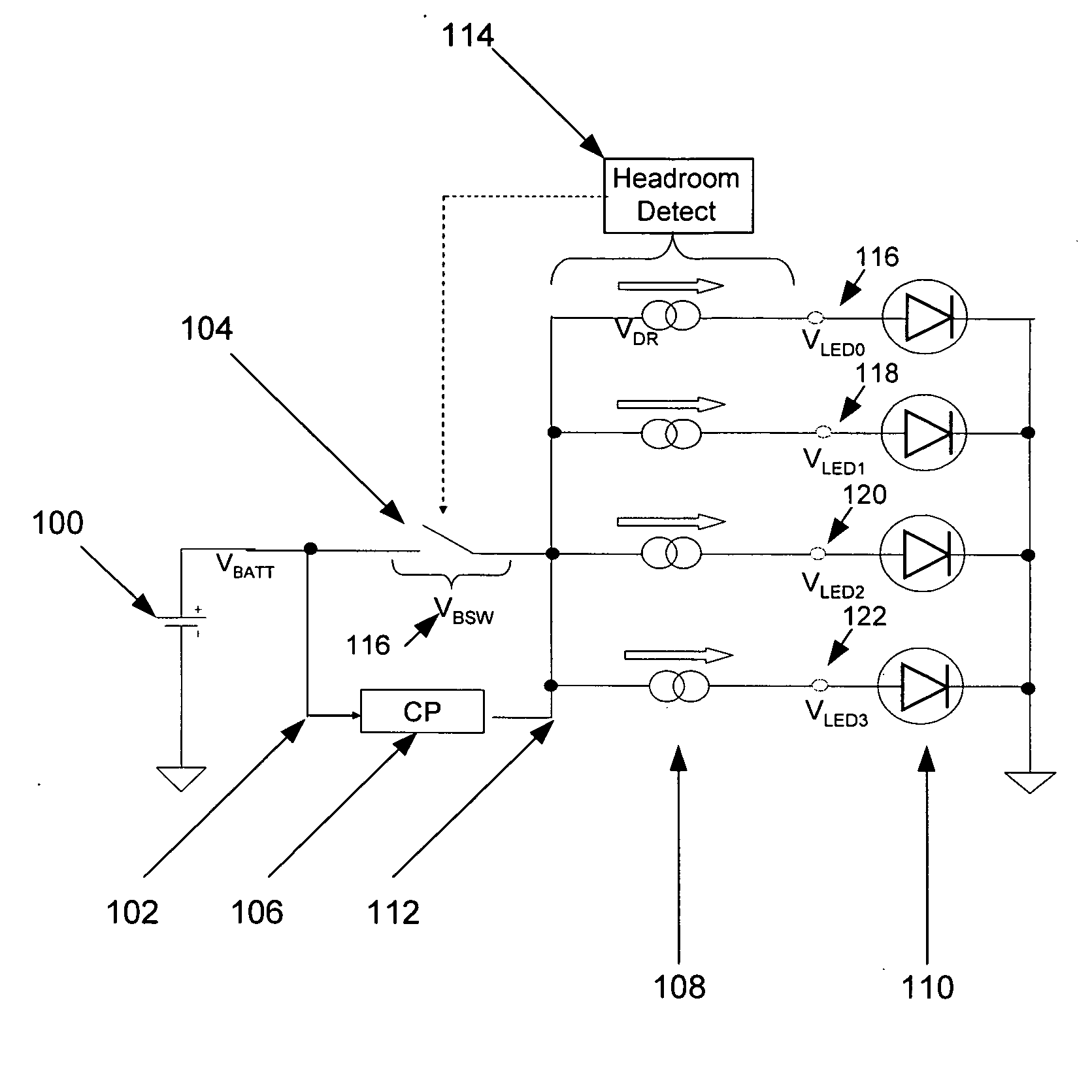
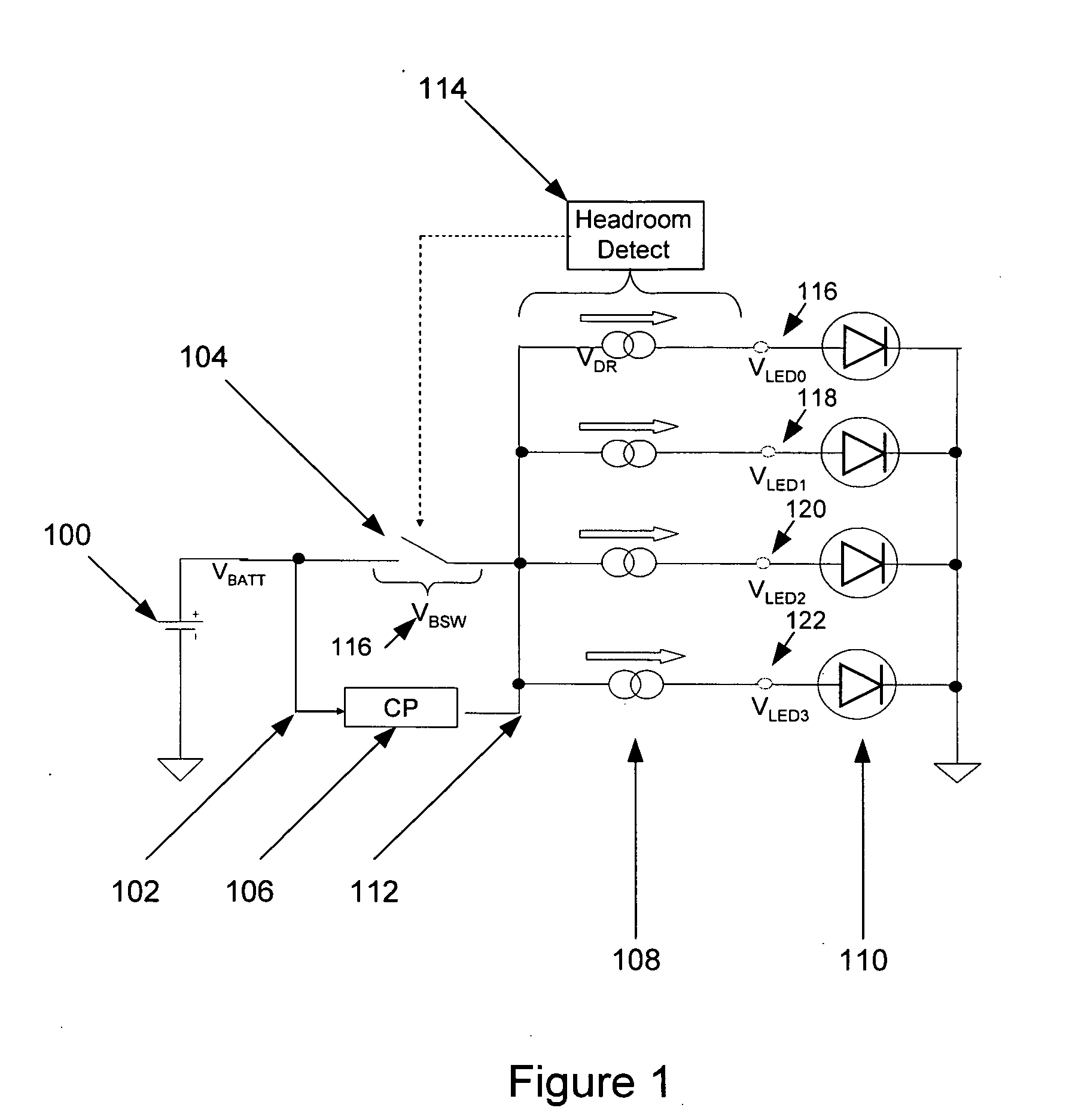
[0019] For the sake of clarity and to better illustrate various aspects of the invention, exemplary embodiments of the invention include one or more white LEDs (“WLEDs”) adapted to ...


PUM


Abstract

An apparatus and method is provided for optimizing LED driver efficiency. The present invention offers low cost solutions for powering LEDs while minimizing overall power dissipation in devices powered by a depletable power source. Low system cost is attained using a charge pump to increase LED drive voltage level and implementing combinations of drive techniques to overcome the inefficiency of the charge pump. A switch bypasses the charge pump when depletable power source output voltage is sufficient to directly drive an LED load. At certain output voltage levels, the switch can be opened causing the charge pump to boost drive voltage. The output voltage may also be PWM modulated to drive the LED load and, at some voltages, the depletable power source may drive the LED load directly. Efficiency levels of 90-97% are attainable.

Description

BACKGROUND OF THE INVENTION [0001] 1. Field of the Invention [0002] The present invention relates to power management and more particularly to power management circuits in integrated circuits and even more particularly to the management and conservation of battery power. [0003] 2. Description of Related Art [0004] Cellular telephones, handheld computers, portable game terminals and other battery-powered devices commonly use Liquid Crystal Display (“LCD”) technology to permit users to receive and review text and graphics information. LCD are often backlit, using light emitting diodes (“LEDs”) to improve display readability while minimizing power usage. However, LEDs operate only when a sufficient voltage is available and illumination intensities are susceptible to variations in battery voltage levels. To reduce the impact of voltage variation on the illumination intensity, a current source is commonly used to drive LEDs at a selected current level. [0005] A common approach to maintai...

Claims


Application Information

Patent Timeline
Patent Type & Authority Applications(United States)
IPC IPC(8): H05B37/00
CPCH05B33/0803H05B33/0809H05B33/0812Y02B20/346H05B33/0818Y02B20/343H05B33/0815H05B45/395H05B45/37Y02B20/30H05B45/325H05B45/347
Inventor EVANS, MICHAELWHITWORTH, ADAM JOHN
Owner ANALOG DEVICES INC
Why Eureka
Try Eureka