Automatic voltage selection for series driven LEDs

a series drive, led technology, applied in the direction of electric variable regulation, process and machine control, instruments, etc., can solve the problems of difficult modification of the electrical characteristics difficulty in maintaining power efficiency, and inability to control the voltage of the led load, so as to reduce the input and output of the driver ic, and simplify the ic design

Inactive Publication Date: 2006-08-24
ANALOG DEVICES INC
View PDF8 Cites 77 Cited by
  • Summary
  • Abstract
  • Description
  • Claims
  • Application Information

AI Technical Summary

Benefits of technology

[0012] The present invention additionally provides a combination of current source and voltage supply, simplifying IC design. In providing for monitoring of the headroom voltage, an associated reduction in input and outputs from a driver IC is also obtained.

Problems solved by technology

However, LEDs operate only when a sufficient voltage is available and illumination intensities tend to vary perceptibly with changes in voltage levels.
As currently implemented, boost regulators suffer from inefficiencies associated with the fixing of the voltage level required to drive an LED load.
By fixing voltage output of the boost regulator, it becomes difficult to modify the electrical characteristics of the LED load and maintain power efficiency.
For example, reduction of a number of series connected LEDs in the LED load 10 may result in power losses in the associated current source causing greater power dissipation and heat generation.
An increase in the number of LEDs in the LED load 10 may result in lower LED illumination and flickering LEDs.
In applications involving portable, battery-operated devices, this loss of efficiency and degraded performance may hinder marketability of the devices.
Additionally, the provision of both a voltage supply pin and a current source or sink pin adds to chip complexity, current handling requirements and heat dissipation.
Further, the substitution of LED types in a production environment may result in performance degradations and undesirable side effects.
For example, replacing an LED type to obtain brighter or differently colored LEDs may result in lower LED operating voltages and increased inefficiency of the voltage booster circuit.
Conversely, an increase in the LED operating voltage may decrease or eliminate the headroom voltage and result in reduced operating current and an associated reduction in LED output.

Method used


Image

  • Automatic voltage selection for series driven LEDs
  • Automatic voltage selection for series driven LEDs
  • Automatic voltage selection for series driven LEDs

Examples


Embodiment Construction

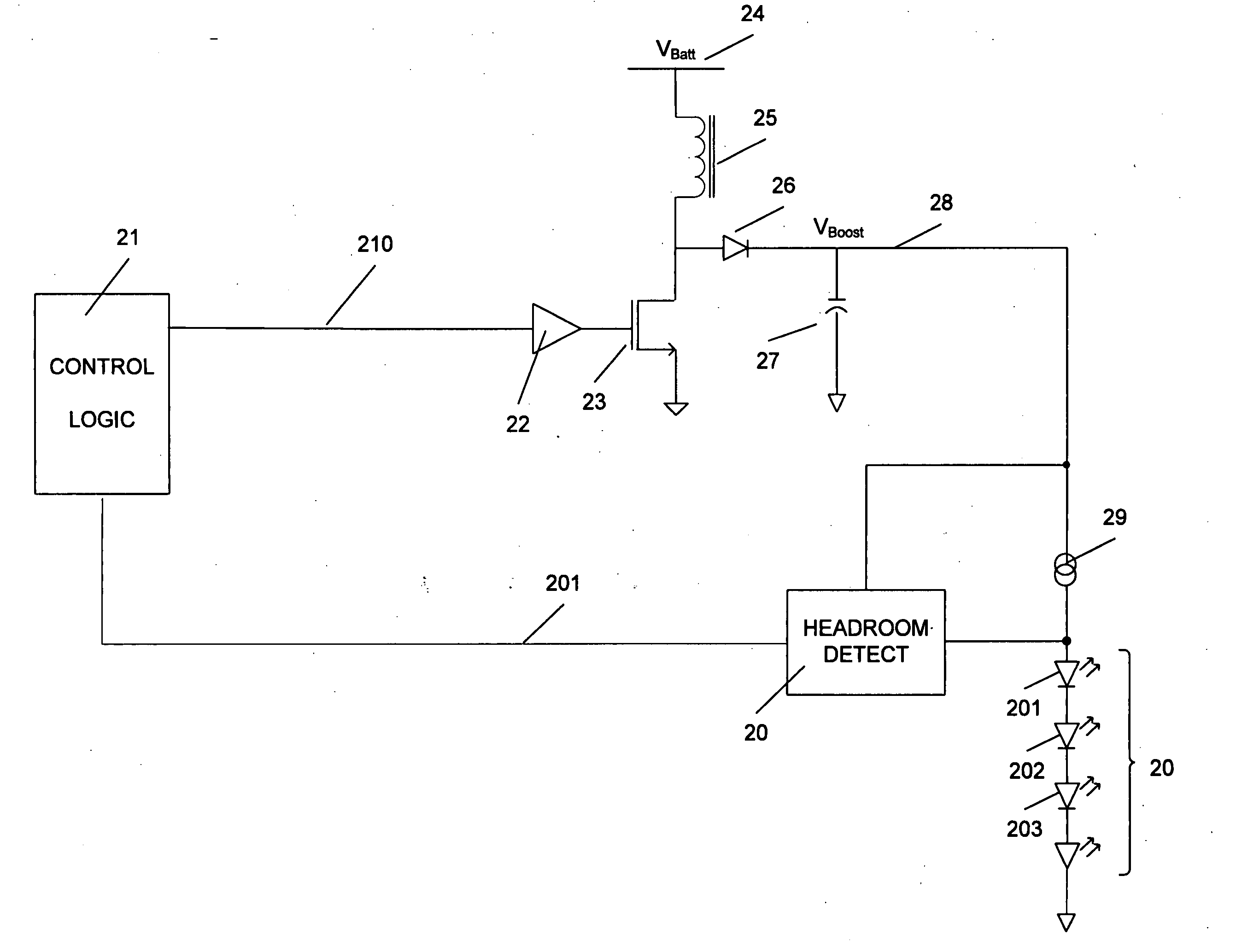
[0020] Embodiments of the present invention will now be described in detail with reference to the drawings, which are provided as illustrative examples so as to enable those skilled in the art to practice the invention. Notably, the figures and examples below are not meant to limit the scope of the present invention. Where certain elements of these embodiments can be partially or fully implemented using known components, only those portions of such known components that are necessary for an understanding of the present invention will be described, and detailed descriptions of other portions of such known components will be omitted so as not to obscure the invention. Further, the present invention encompasses present and future known equivalents to the components referred to herein by way of illustration. For the sake of clarity and consistency, reference numerals will be repeated in various drawings where elements of the drawings are of similar construction and purpose.

[0021] For t...


PUM


Abstract

An apparatus and method for automatically controlling voltages used to drive LED loads. A battery voltage can be boosted to a selected drive voltage level connected to current sources for driving the LED loads. The drive voltage level is selected by a controller using a headroom detect component to measure a headroom voltage across the current source. The controller adjusts the drive voltage level to maintain the headroom voltage within a predetermined operating range. The drive voltage may be used to drive a variable number of LEDs or a plurality of different LED loads connected in parallel without manual readjustment of drive voltage.

Description

CROSS-REFERENCE TO RELATED APPLICATION [0001] This application claims the benefit of prior U.S. Provisional Application Ser. No. 60 / 650,925, filed Feb. 7, 2005 and U.S. Provisional Application Ser. No. 60 / 650,945, filed Feb. 7, 2005, both provisional applications incorporated herein by reference. The present application is also related to the copending U.S. Utility Patent Application ______, entitled Regulating Switching Regulators By Load Monitoring, filed on even date herewith and incorporated herein by reference.BACKGROUND OF THE INVENTION [0002] 1. Field of the Invention [0003] The present invention relates to power management and more particularly to power management of LED driver circuits. [0004] 2. Description of Related Art [0005] Cellular telephones, handheld computers, portable game terminals and other battery-powered devices commonly use Liquid Crystal Display (“LCD”) technology to permit users to receive text and graphics information. LCDs often use light emitting diodes...

Claims


Application Information

Patent Timeline
Patent Type & Authority Applications(United States)
IPC IPC(8): H05B41/36
CPCH02M3/156H02M3/157H02M2001/0048H05B33/0815H05B33/0827Y02B20/346Y02B20/347Y02B70/1491H05B45/38H05B45/46H02M1/0048Y02B20/30Y02B70/10
Inventor SHAMI, HASSAN B.WHITWORTH, ADAM JOHN
Owner ANALOG DEVICES INC
Why Eureka
Try Eureka