
Automatic homing systems and other sensor systems

Inactive Publication Date: 2006-10-05
SRS TECH
View PDF11 Cites 79 Cited by
  • Summary
  • Abstract
  • Description
  • Claims
  • Application Information

AI Technical Summary

Benefits of technology

[0007] The present inventor has solved a group of homing problems by inventive homing systems applicable to pairs of objects (such as, e.g., ground vehicles, watercraft, aircraft, spacecraft, etc.) wherein one or both of the objects are moving (such as moving in two-dimensions or three-dimensions) and one or both of the objects may be unmanned. Examples of objects to which the present invention may be applied may be a ground vehicle, watercraft, aircraft, spacecraft, an object worn by or attached to a person, etc., wherein objects used in a pair may be the same or different (i.e., a pair of ground vehicles or a pair consisting of a ground vehicle and another object). In the present invention, wh

Problems solved by technology

In a leader-follower application, the problem of causing the follower vehicle to properly home in on the leader vehicle has been complicated.
A simple solution for automatic homing in leader-follower application has been elusive.

Method used


Image

  • Automatic homing systems and other sensor systems
  • Automatic homing systems and other sensor systems
  • Automatic homing systems and other sensor systems

Examples


##ventive example 1

Inventive Example 1

(Multiple Light Automatic Direction Finder (mLADF))

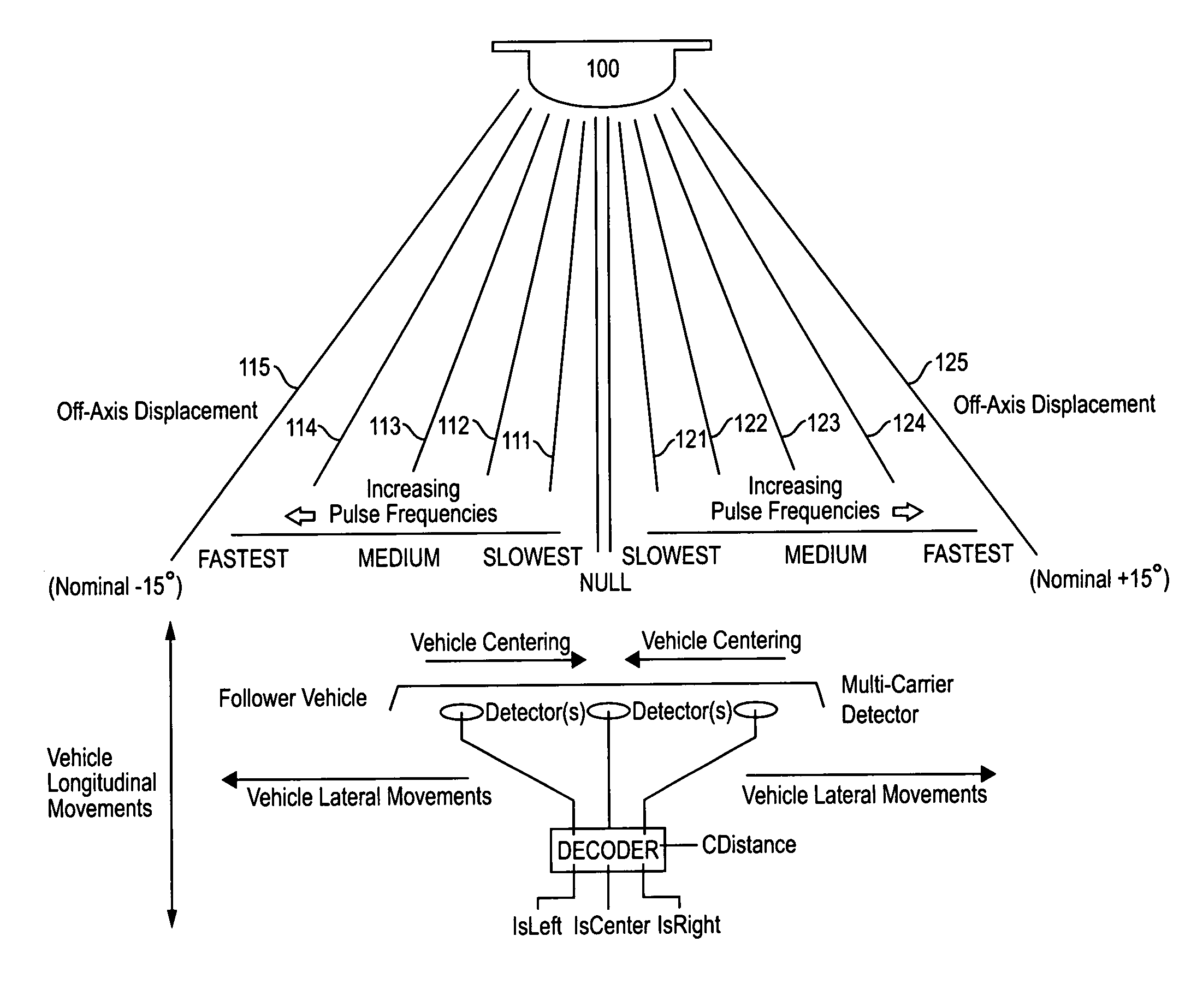
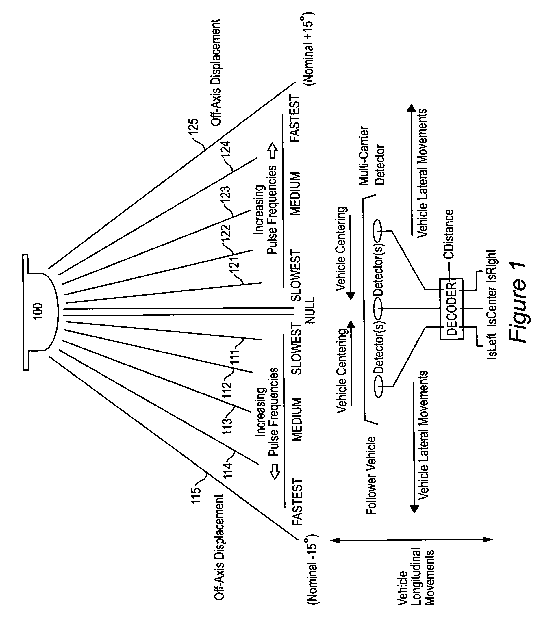
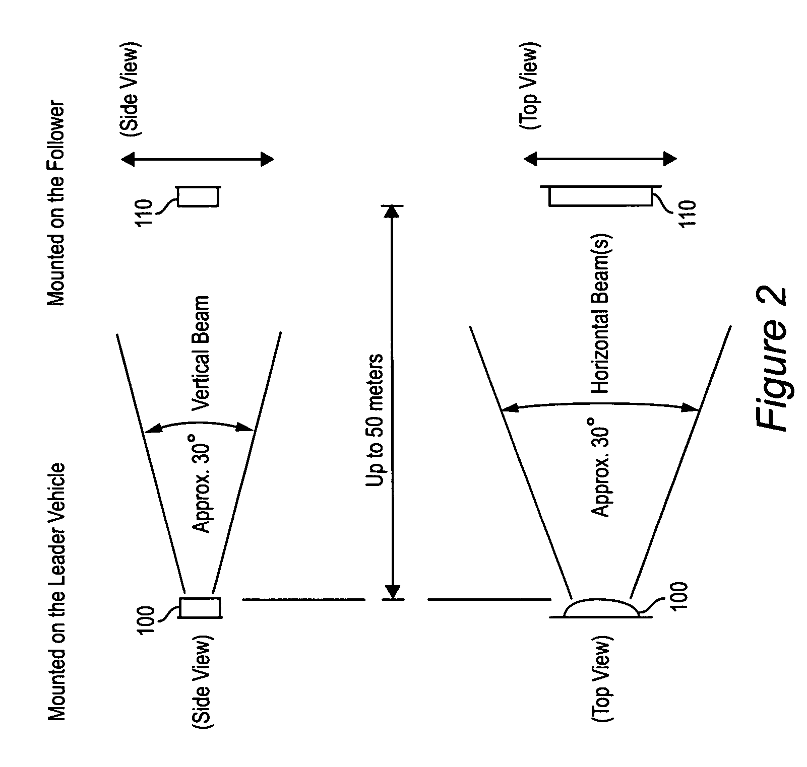
[0032] An emitter / sensor system has been designed that is a multiple Light Automatic Direction Finder (mLADF). The mLADF system of this Example 1 consists of a light source (emitter) assembly and a multi-carrier detector (sensor) assembly. The purpose of the mLADF system is to provide a set of signaling outputs that encode the longitudinal and lateral spatial relationships between two self-propelled, ballistic, and / or tethered vehicles in any combination. The system may be applied in space-based, airborne, and ground vehicle homing, or in convoy settings. When used by ground vehicles to accomplish a convoy relationship, the function is sometimes referred to as “leader-follower.” The installation of an mLADF sensor system can be physically separable from, and will operate irrespective of, the vehicle(s) with which it is used. Operation of the mLADF system does not require the source / leader or homing / follower vehic...

example 1a

Inventive Example 1A

(Three Dimensions)

[0055]FIGS. 1 and 2 can be extended to three-dimensional space, such as, for example, in a case where a second ship is homing in on a first ship. By mounting an additional emitter on the first ship, homing can be accomplishing in a up / down direction as well as in a left / right direction. Therefore, velocity of the second ship also can be controlled.

[0056] A preferred use of the present invention is to deploy automated robotic-type vehicles, especially in convoys and especially in dangerous situations, without needing human operators. Convoys of vehicles in leader-follower configuration advantageously may be operated without needing human operators in the follower vehicles. It will be appreciated that the invention additionally has other uses and applications.


PUM


Abstract

Automatic homing systems are disclosed, operable between pairs of objects. One or both of the objects in the pair may be moving and / or unmanned. Examples of a pair of objects between which the inventive automatic homing systems may be operated are ground vehicles in leader-follower configuration, as well as aircraft, spacecraft, watercraft. The automatic homing systems are based on a relatively simple, elegant concept of rightness / leftness and a line-of-sight link between a respective leader vehicle and follower vehicle. Complex EO / IR cameras, LIDAR, RADAR, and / or SONAR-based sensor systems can be avoided. Convoys of vehicles in leader-follower configuration advantageously may be operated without needing human operators in the follower vehicles.

Description

RELATED APPLICATION [0001] This claims benefit of U.S. provisional application Ser. No. 60 / 668,068 filed Apr. 5, 2005 titled “Sensor System.”FIELD OF THE INVENTION [0002] The present invention generally relates to automatic direction finding sensor systems, especially to vehicular leader-follower systems and other automatic homing systems. BACKGROUND [0003] Certain leader-follower vehicle applications have been disclosed, of which ground vehicle convoys and unmanned robotic vehicles are particularly mentioned. The following are mentioned as examples of leader-follower applications disclosed in the patent literature: [0004] U.S. Pat. No. 5,521,817 by Burdoin et al. issued May 28, 1996 to Honeywell, Inc. for “Airborne drone formation control system,” discloses remote controlled drones. The follower drone is said to control itself to follow the movements of its leader. Use of GPS is mentioned. [0005] U.S. Pat. No. 6,842,674 by Solomon issued Jan. 11, 2005 for “Methods and apparatus for...

Claims


Application Information

Patent Timeline
IPC IPC(8): G01C3/08G01B11/26
CPCG01C3/08
Inventor ROULY, OVI CHRIS
Owner SRS TECH
Learn More