Objectives as a microlithography projection objective with at least one liquid lens

a technology of liquid lens and object, applied in the direction of microlithography exposure apparatus, instruments, photomechanical treatment, etc., can solve the problems of limited success and refractive index

Inactive Publication Date: 2006-10-05
CARL ZEISS SMT GMBH
View PDF6 Cites 68 Cited by
  • Summary
  • Abstract
  • Description
  • Claims
  • Application Information

AI Technical Summary

Benefits of technology

[0045] This permits, inter alia, greater freedom in configuring the passage of the light bundles next to the mirrors, and yields an additional diaphragm location which can well be situated in an air space and is therefore well suited as a stop-down aperture diaphragm.
[0046] It is to be seen i

Problems solved by technology

Lenses made from sapphire have a high refractive index but are birefringent,

Method used


Image

  • Objectives as a microlithography projection objective with at least one liquid lens
  • Objectives as a microlithography projection objective with at least one liquid lens
  • Objectives as a microlithography projection objective with at least one liquid lens

Examples


Embodiment Construction

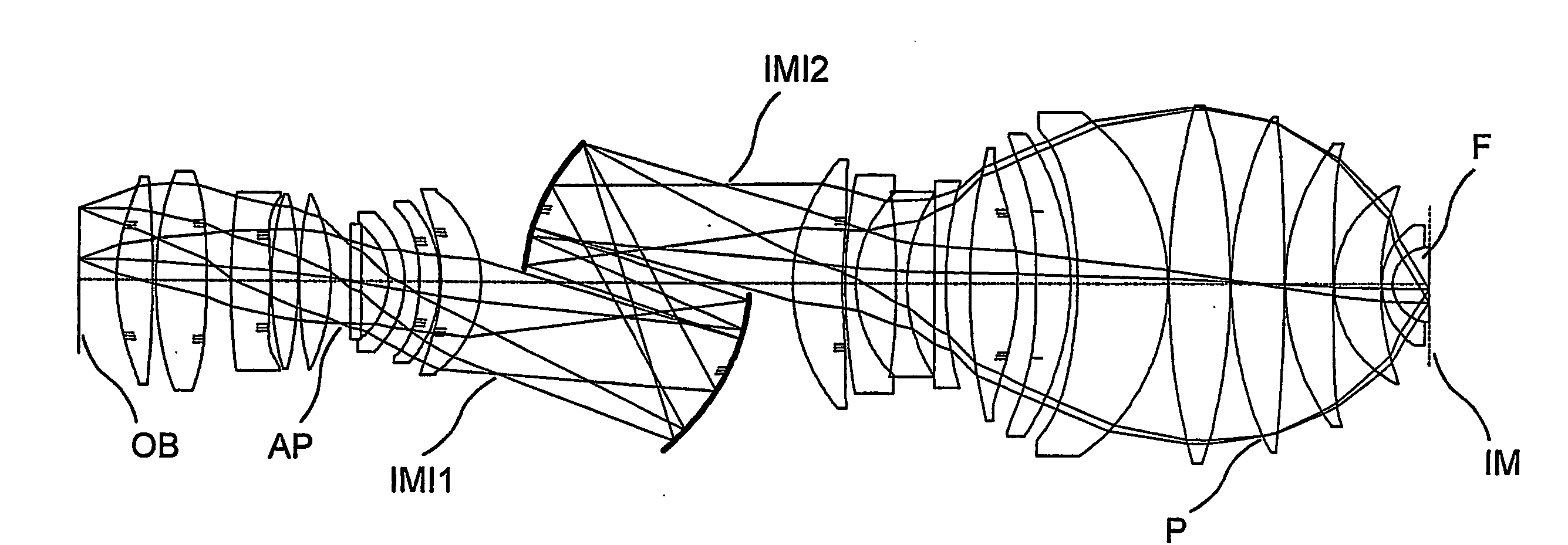
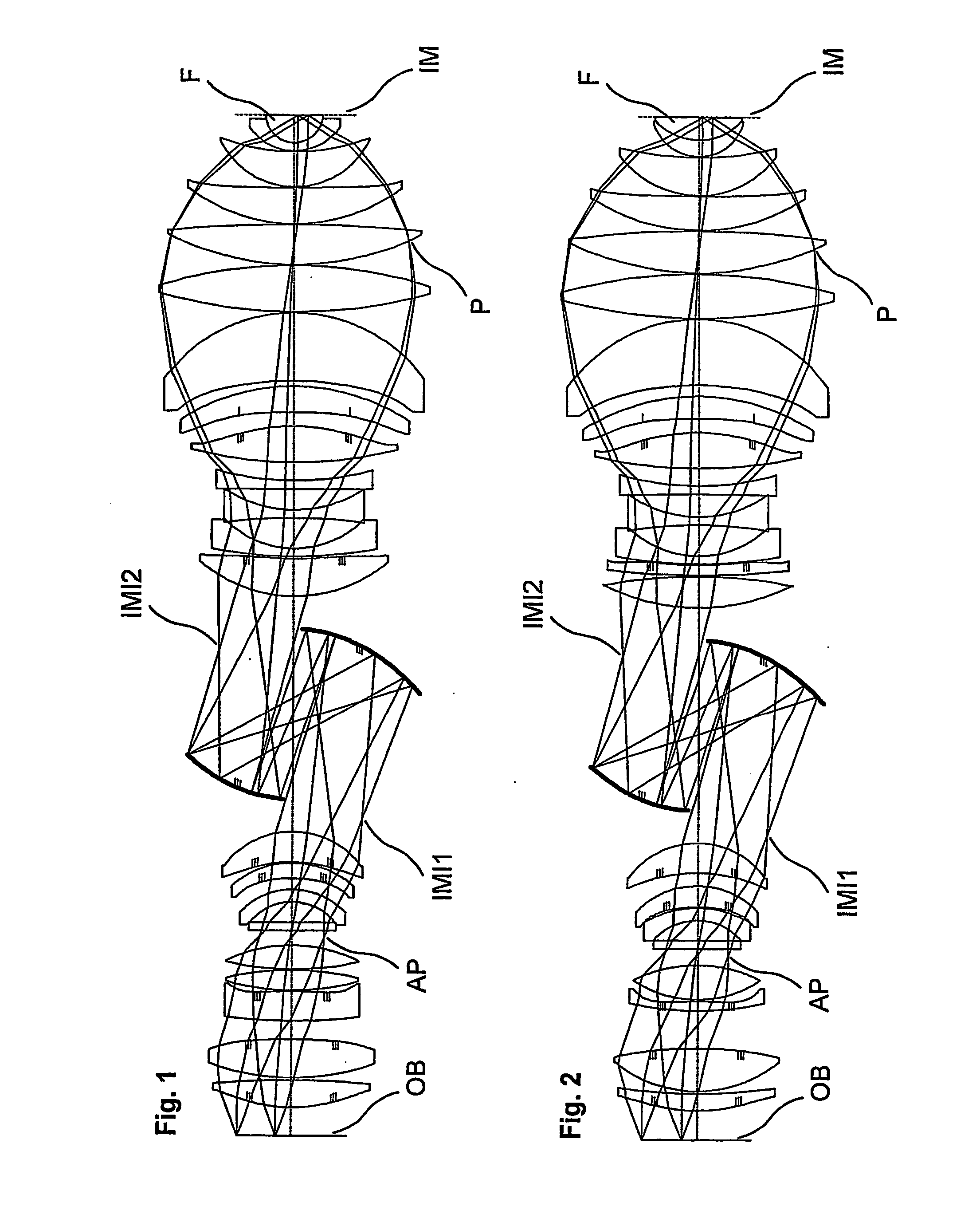
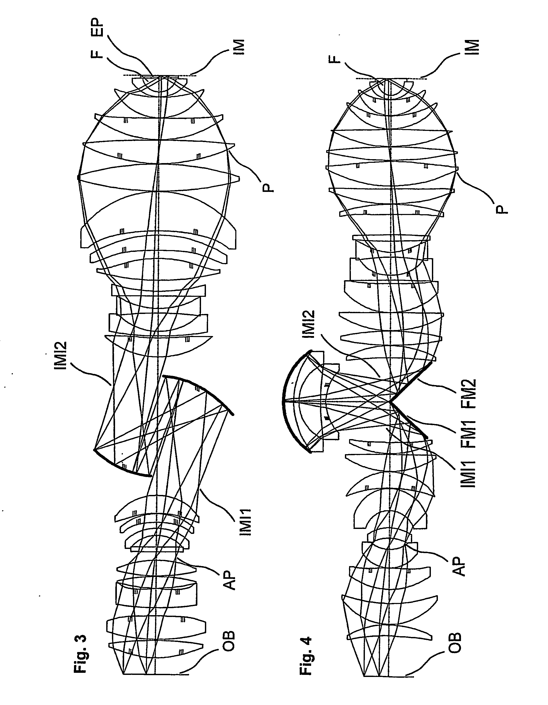
[0055] In FIG. 1 to 6 marginal and principal rays are depicted for the object points nearest and furthest from the axis. Aspheric surfaces are marked twice with 3 lines at the contour.

[0056] The optical axis or the axis of symmetry of the curvatures of the surfaces is marked by dots and dashes.

[0057] In each case OB denotes the object plane. This corresponds to the surface (SURF) 0 in the tables. IM denotes the image plane and corresponds in each case to the surface of the highest number in the tables.

[0058] F respectively denotes the liquid lens according to the invention.

[0059] EP denotes an optional end plate.

[0060] IMI1 and IMI2 are the intermediate images.

[0061] AP denotes the position of the system aperture at which an adjustable diaphragm can be arranged and will also be referred to as diaphragm plane.

[0062] P denotes the pupil in an image-side objective part.

[0063] All embodiments shown are designed for the operating wavelength 193.4 nm (ArF Excimer Laser) and reduce...


PUM


Abstract

The invention relates to an objective designed as a microlithography projection objective for an operating wavelength. The objective has a greatest adjustable image-side numerical aperture NA, at least one first lens made from a solid transparent body, in particular glass or crystal, with a refractive index nL and at least one liquid lens (F) made from a transparent liquid, with a refractive index NF. At the operating wavelength the first lens has the greatest refractive index nL of all solid lenses of the objective, the refractive index nF of the at least one liquid lens (F) is bigger than the refractive index nL of the first lens and the value of the numerical aperture NA is bigger than 1.

Description

[0001] The complete disclosure of U.S. application Ser. No. 10 / 734,623 filed on Dec. 15, 2003, International Application No. PCT / EP2004 / 005816 filed on May 28, 2004, U.S. application Ser. No. 60 / 530,623 filed on Dec. 19, 2003, U.S. application Ser. No. 60 / 530,978 filed on Dec. 22, 2003, European Application No. 03256499.9 filed on Oct. 15, 2003, U.S. application Ser. No. 60 / 544,967 filed on Feb. 13, 2004, U.S. application Ser. No. 60 / 592,208 filed on Jul. 29, 2004, U.S. application Ser. No. 60 / 568,006 filed on May 4, 2004, U.S. application Ser. No. 60 / 591,775 filed on Jul. 27, 2004 and U.S. application Ser. No. 60 / 612,823 filed on Sep. 24, 2004 is hereby incorporated.BACKGROUND OF THE INVENTION [0002] 1. Field of the invention [0003] The invention relates to an objective designed as a microlithography projection objective. The objective according to the invention comprises at least one liquid lens made from a transparent liquid. [0004] 2. Description of the Related Art [0005] Microl...

Claims


Application Information

Patent Timeline
IPC IPC(8): G02B3/00G03F7/20
CPCG02B3/12G02B17/0812G02B17/0856G03F7/70966G03F7/70241G03F7/70341G03F7/70958G03F7/70225G02B13/14G02B13/18G02B17/08G03F7/20
Inventor SHAFER, DAVID R.BEDER, SUSANNESCHUSTER, KARL-HEINZ
Owner CARL ZEISS SMT GMBH
Why Eureka
Try Eureka