Fixed scroll of scroll compressor

Inactive Publication Date: 2006-10-05
LG ELECTRONICS INC
View PDF10 Cites 17 Cited by
  • Summary
  • Abstract
  • Description
  • Claims
  • Application Information

AI Technical Summary

Benefits of technology

[0013] Therefore, the present invention has been made in view of the above problems, and it is an object of the present invention to provide a fixed scroll of a scroll compressor whic

Problems solved by technology

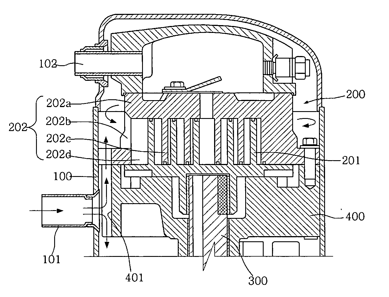
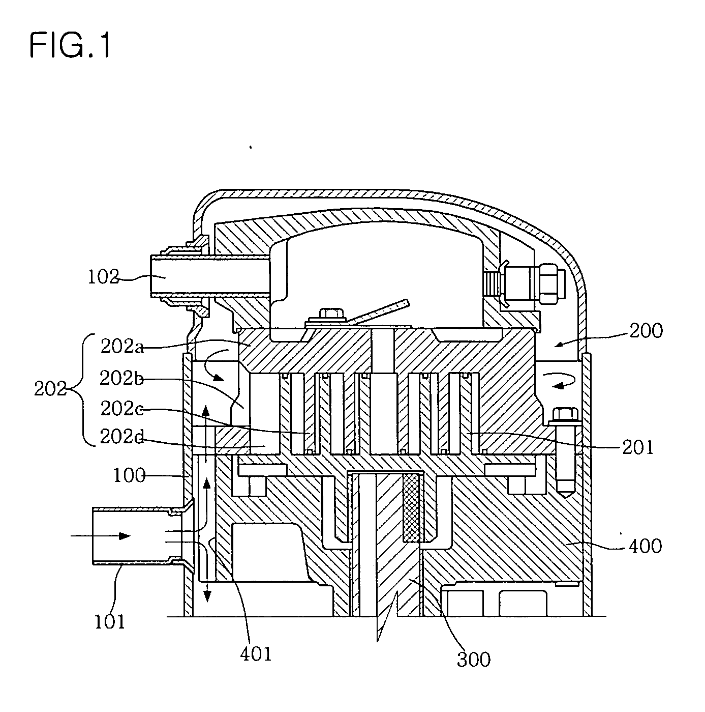
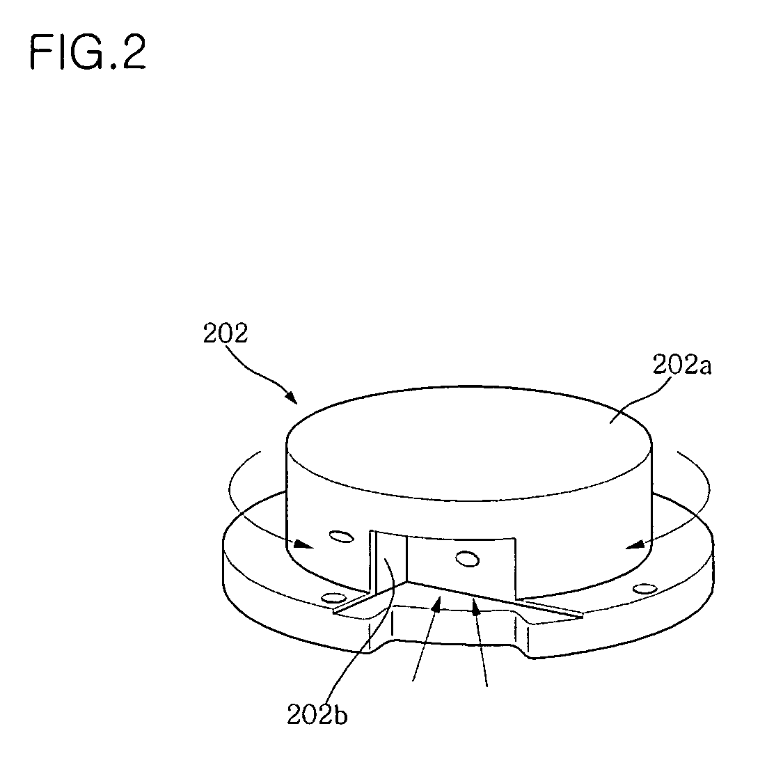
The conventional scroll compressor configured as stated above, however, has a problem that suctioned gaseous refrigerant, that strikes the suction baffle, is not introduced directly into the compression chamber, but is circulated along an outer circumference

Method used


Image

  • Fixed scroll of scroll compressor
  • Fixed scroll of scroll compressor
  • Fixed scroll of scroll compressor

Examples


Embodiment Construction

[0026] Now, a preferred embodiment of the present invention will be explained with reference to the accompanying drawings.

[0027]FIG. 3 is a bottom perspective view of a fixed scroll in accordance with the present invention. FIG. 4 is a perspective view illustrating the fixed scroll of FIG. 3, which is coupled to a main frame.

[0028] As shown in FIGS. 3 and 4, the fixed scroll 1 of a scroll compressor includes a scroll body 10 arranged on an upper surface of a main frame 2 and defining a compression chamber 11 therein, and an interceptive suction portion 20 formed at the scroll body 10 to guide gaseous refrigerant into the compression chamber 11.

[0029] The scroll body 10 has an involuted wrap 12 to define the compression chamber 11 therein, and a mounting flange 13 formed around a lower end of the scroll body 10 to be mounted on the upper surface of the main frame 2.

[0030] The interceptive suction portion 20 serves to guide only suctioned gaseous refrigerant, that is directed upwa...


PUM


Abstract

Disclosed herein is a scroll compressor, and more particularly, a fixed scroll of the scroll compressor which can allow part of gaseous refrigerant to be smoothly introduced into a compression chamber while preventing introduction of the remaining gaseous refrigerant that is heated in the compressor. The fixed scroll includes a scroll body having an involuted wrap to define a compression chamber therein and provided, around a lower end thereof, with a mounting flange to be arranged on an upper surface of a main frame, and an interceptive suction portion configured to guide part of the gaseous refrigerant, that is directed upward along the main frame, into the compression chamber while preventing introduction of the remaining gaseous refrigerant that is circulated around the scroll body.

Description

CROSS REFERENCE TO RELATED APPLICATIONS [0001] Pursuant to 35 U.S.C. § 119(a), this application claims the benefit of earlier filing date and right of priority to Korean Patent Application No. 10-2005-0026583, filed on Mar. 30, 2005, the content of which is hereby incorporated by reference herein in its entirety. BACKGROUND OF THE INVENTION [0002] 1. Field of the Invention [0003] The present invention relates to a scroll compressor, and more particularly, to a fixed scroll of a scroll compressor which can allow gaseous refrigerant, that is introduced into a compressor shell via a suction pipe, to be directly introduced into a compression chamber without being heated. [0004] 2. Description of the Related Art [0005]FIG. 1 is a longitudinal sectional view illustrating important parts of a conventional scroll compressor. FIG. 2 is a perspective view illustrating a fixed scroll of FIG. 1. [0006] Arrows shown in FIGS. 1 and 2 indicate a flow direction of suctioned gaseous refrigerant. [00...

Claims


Application Information

Patent Timeline
IPC IPC(8): F01C1/02F04C2/00
CPCF04C18/0253F04C2250/101F04C23/008F04C18/02
Inventor NAM, JUNG-WONYOO, BYUNG-KIL
Owner LG ELECTRONICS INC
Why Eureka
Try Eureka